
This is DTC which is related with communication error between BCM and other units.
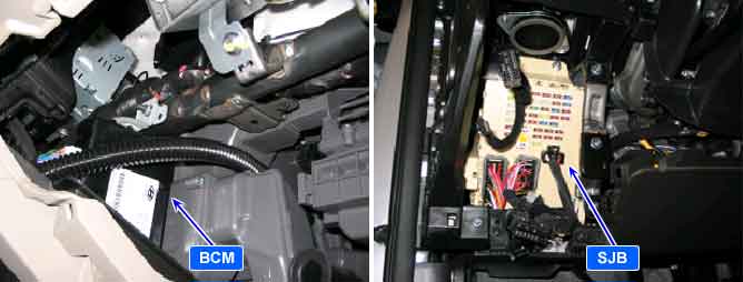
※ Body CAN communication Control Units : BCM(Body Control Module), CLU(Cluster), PSM(Power Seat Module), SMK(Smart Key), SJB(Smart Junction Box), PTM(Power Tail gate Module).
*¹ CAN (Controller Area Network) : CAN is serial bus communication type which links not only communication system but also control units each other.
This code is outputted when BCM can't receive data from SJB by CAN Line for 10 sec.
Item | Detecting Condition | Possible Cause |
DTC Strategy |
•
CAN Comm. Check (BCM ↔ SJB) | 1. IG ON (1) No receiving CAN Data owing to BUS OFF (Check CAN BUS ERROR DTC is being.) (2) BCM CAN High/Low Lines open together (3) Check SJB (Including the related fuses) (4) SJB CAN High/Low Lines open |
Enable Conditions |
•
BCM power on | |
Threshold Value |
•
No message from SJB to BCM for 10 sec. | |
Diagnostic Time |
•
More than 10 sec | |
DTC Erasing Time |
•
DTC is erased immediately after receiving data from FAM |
Fig 1) CAN Low/High Signal Waveform
Fig 2) CAN BUS VOLTAGE LEVEL (LOW SPEED CAN)