
Input speed sensor value must be equal Output speed sensor value times each gear ratio at each gear position of trasmission. That operation value equal with TCM operation value. For example Output speed sensor value is 1000RPM and 5th speed gear ratio is 1.0 then Input speed sensor value must be 1000 RPM.
This code is set when Input speed sensor value is different with TCM operation value, caused by control valve sticking, solenoid valve fault(most of fault is mechanical, rarely electrical fault).
Item | Detecting Condition | Possible Cause |
DTC Strategy |
•
5th gear incorrect gear ratio |
•
Input speed sensor fault
•
Output speed sensor fault
•
Clutch slip in Transmission ( 3/5/R clutch, OD clutch) or oil pressure controller fault |
Enable Conditions |
•
Solenoid power voltage> 10V
•
Oil Temperature Sensor >-10℃
•
Time after shift changing finish > 1sec
•
Engine speed >400rpm
•
Output speed >200rpm
•
Input speed > 0rpm
•
Shift stage 5th. gear
•
TR switch = "D"range | |
Threshold value |
•
Output speed>(input speed+200rpm)/5th. gear ratio
•
Output speed<(input speed-200rpm)/5th. gear ratio | |
Detecting Time |
•
1 sec and 4 times | |
Fail safe |
•
Locked into 4th gear |
Solenoid | ||||||
SS-A | SS-B | OD N-H | 35R N-H | UD N-H | 26 N-L | |
N,P | ○ | ○ | ○ | ○ | ||
1st | ○ | △ | ○ | |||
2nd | ○ | ○ | ○ | |||
3rd | ○ | ○ | ||||
4th | ○ | |||||
5th | ○ | ○ | ||||
6th | ○ | ○ | ○ | |||
L | ○ | ○ | ||||
REV | ○ | ○ | △ | ○ | ||
○ : Connected status
△ : Connedted at Vehicle speed above 8km/h
Clutch | Brake | |||||
35R | OD C | 26 B | UD B | LR B | O.W. | |
P,N | ● | |||||
R | ● | ● | ||||
D1 | ● | ○ | ● | |||
D2 | ● | ● | ||||
D3 | ● | ● | ||||
D4 | ● | ● | ||||
D5 | ● | ● | ||||
D6 | ● | ● | ||||
○ : Operated at Vehicle speed under 5km/h
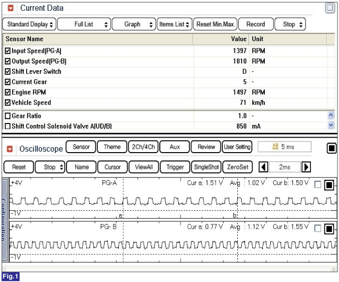
Fig 1) "D" range 5th gear
