2.
Start the engine and check for signal waveform compared with reference waveform as below.
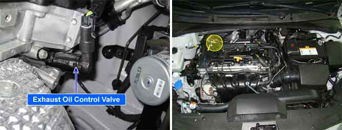
The CVVT (Continuously Variable Valve Timing) system is installed to the chain sprocket of the exhaust camshaft. There is no variation in valve timing of the exhaust cam because the exhaust camshaft is driven by the timing belt. The timing of the intake cam is varied by the relative operation the CVVT vane to the housing. The CVVT controller regulates the intake camshaft angle using oil pressure through the OCV(Oil Control Valve). As result, the relative position between the camshaft and the crankshaft becomes optimal, and the engine torque improves, fuel economy improves, exhaust emissions decrease by changing the valve open/close timing of the intake camshaft.
The deviation of the camshaft position from the target point is evaluated during stable driving condition. The PCM accumulates this deviation for a certain period and sets DTC P0014 when the accumulated deviation is too high. The target camshaft position is predetermined value depending on engine speed and throttle angle in the PCM.
Item | Detecting Condition | Possible Cause | |
DTC Strategy | Case1 |
•
Deviation check between actual CAM position and CAM setpoint position in case of changing setpoint (slow response of actuator) | 1. Oil leak 2. Oil Control Valve 3. CVVT Assembly |
Case2 |
•
Deviation check between actual CAM position and CAM setpoint position (steady deviation) | ||
Enable Conditions | Case1 |
•
CVVT control active
•
Camshaft setpoint moving by more than 12°CRK within less than 0.70 sec.
•
Camshaft setpoint moved more than 5 times since engine start
•
11V < Battery voltage < 16V
•
600 to 1500< Engine speed(RPM) < 5000
•
No relevant failure
•
20℃(68℉) < Engine oil temp. < 110℃(230℉) | |
Case2 |
•
CVVT control active
•
Camshaft setpoint moved more than 5 times since engine start
•
Camshaft setpoint not close to full retard position
•
11V < Battery voltage < 16V
•
600 to 1500 < Engine speed(RPM) < 5000
•
No relevant failure
•
20℃(68℉) < Engine oil temp. < 110℃(230℉) | ||
Threshold Value | Case1 |
•
CAM position movement < 3.4 °CRK within 0.8 sec. (with CAM setpoint moving by 12 °CRK) | |
Case2 |
•
Integral of Camshaft position actual value - Camshaft position setpoint > 45°CRK/sec. | ||
Diagnostic Time | Case1 |
•
600 sec. | |
Case2 |
•
180 sec. | ||
MIL On Condition |
•
2 Driving Cycles | ||
Intake OCV | Normal Parameter |
Insulation Resistance (Ω) | Above 50 ㏁ |
Temp.(℃) | Temp.(℉) | Resistance(Ω) | Temp.(℃) | Temp.(℉) | Resistance(Ω) |
0 | 32 | 6.2 ~ 7.4 | 60 | 140 | 8.0 ~ 9.2 |
10 | 50 | 6.5 ~ 7.7 | 70 | 158 | 8.3 ~ 9.5 |
20 | 68 | 6.9 ~ 7.9 | 80 | 176 | 8.6 ~ 9.8 |
30 | 86 | 7.1 ~ 8.3 | 90 | 194 | 8.9 ~ 10.1 |
40 | 104 | 7.4 ~ 8.6 | 100 | 212 | 9.2 ~ 10.4 |
50 | 122 | 7.7 ~ 8.9 |
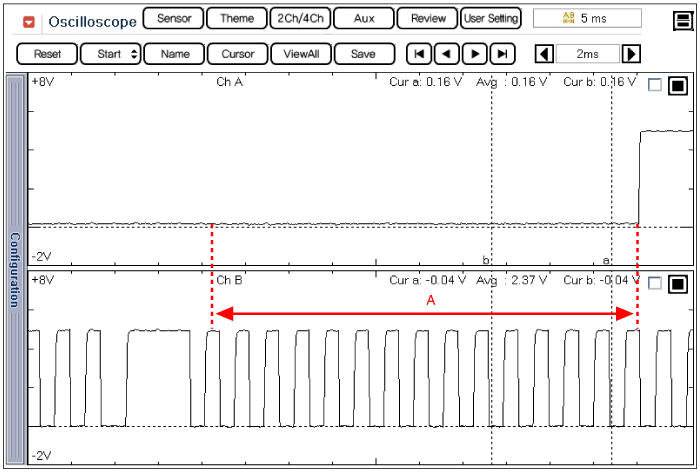
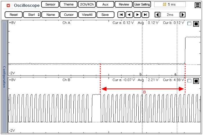
Set up an oscilloscope as follows :
Channel A (+): Signal terminal of the CMPS #2(back probe), (-): ground
Channel B (+): Signal terminal of the CKPS(back probe), (-): ground
Start the engine and check for signal waveform compared with reference waveform as below.
A : CMPS and CKPS waveform of exhaust shaft at idle
B : CMPS and CKPS waveform of exhaust cam shaft at acceleration
(Tooth number is changed by CVVT operation)

