Monitor "Diagnostic Trouble Codes(DTC)" with GDS.

Connect GDS to Data Link Connector(DLC).
Ignition "ON"
Monitor "Diagnostic Trouble Codes(DTC)" with GDS.

Is DTC status displayed as Present?
 | ▶ Go to "Monitor GDS Data" procedure. |
 | ▶ Go to "Verification of Vehicle Repair" procedure. |
Ignition switch "OFF"
Connect VMI to GDS and set up the Oscilloscope.(2 Channel):
Channel A (+) : injector control low terminal (Injector Harness Connector)
Channel A (-) : Ground
Channel A (+) : Injector control high terminal (Injector Harness Connector)
Channel A (-) : Ground
Aux : Measure the current on "Injector Control Low" wire with low current sensor
Ignition switch "ON" & Engine "ON"
Inspection condition : Engine "ON" & Engine speed Approx. 3,000RPM
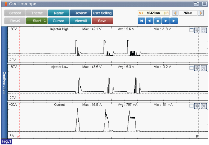
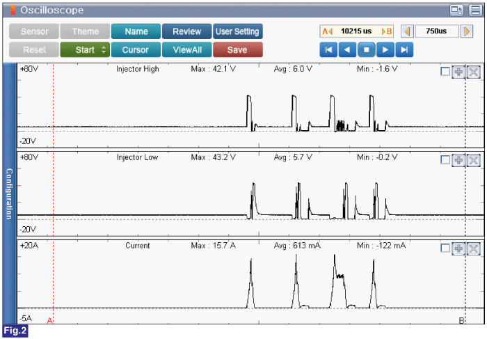
Specification :Refer to figure below


Fig.1) Injector control low/high signal waveform and current under engine idle. (2 Pilot injection, 1 main injection)
Fig.2) Injector control low/high signal waveform and current under engine speed approx. 3,000RPM. (2 Pilot injection, 1 main injection and 1 post injection)
Is the measured value within specification?
 | ▶ Fault is intermittent caused by poor contact in the sensor's and/or ECM's connector or was repaired and ECM memory was not cleared. Thoroughly check connectors for looseness, poor connection, bending, corrosion, contamination, deterioration, or damage. Repair or replace as necessary and go to "Verification of vehicle Repair" procedure. |
 | ▶ Go to "Wiring Inspection" procedure. |