Ignition switch "OFF"
Connect VMI to GDS and set up the Oscilloscope.(2 Channel):
Channel A (+) : APS 1 signal terminal (APS Harness Connector)
Channel A (-) : Ground
Channel B (+) : APS2 signal terminal (APS Harness Connector)
Channel B (-) : Ground
Ignition switch "ON" & Engine "OFF"
Operate the APS
Specification :Refer to table below
Item | Output Voltage (V) (Vref = 5.0V) | |
APS1 | APS2 | |
Not pressed (V) | Approx. 0.7 ~ 0.8 | Approx 0.29 ~ 0.46 |
Fully pressed (V) | Approx. 3.85 ~ 4.35 | Approx. 1.93 ~ 2.18 |
Is the measured value within specification?
![]() | ▶ Fault is intermittent caused by poor contact in the sensor's and/or ECM's connector or was repaired and ECM memory was not cleared. Thoroughly check connectors for looseness, poor connection, bending, corrosion, contamination, deterioration, or damage. Repair or replace as necessary and go to "Verification of vehicle Repair" procedure. |
![]() | ▶ Carefully re-do this troubleshooting guide steps. ▶ If no problems were found with the circuits or connectors, replace the APS and go to "Verification of Vehicle Repair" procedure. |
When installing component, tighten it within specification
If component is dropped, check for proper operation. The internal damage may be present
When APS is replaced, perform "Essential work after component replacement. Otherwise, vehicle performance and emission control may not work properly until auto learning is completed
Ignition switch "OFF"
Connect GDS to Data Link Connector(DLC).
Ignition Switch "ON" & Engine "OFF"
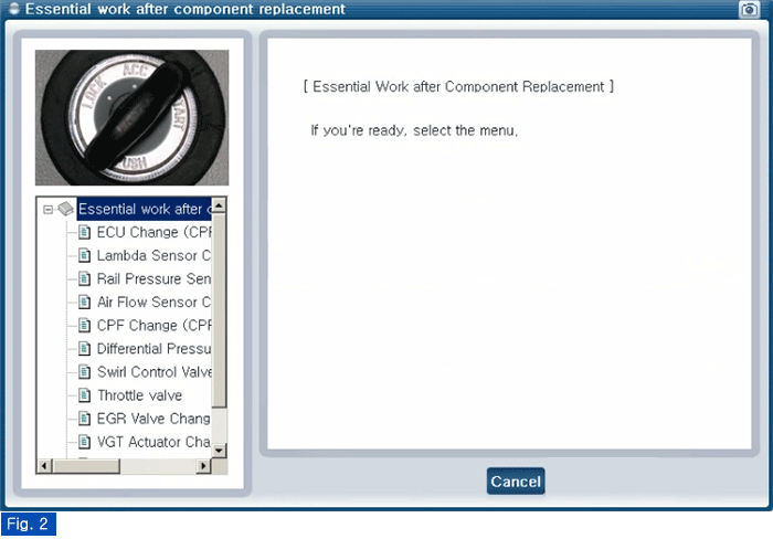
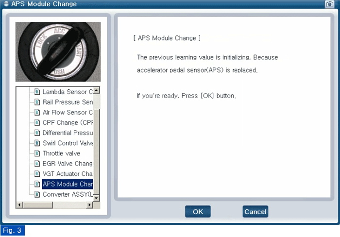
Perform "Essential Work After Component Replacement" in "Vehicle Software Management" with GDS.
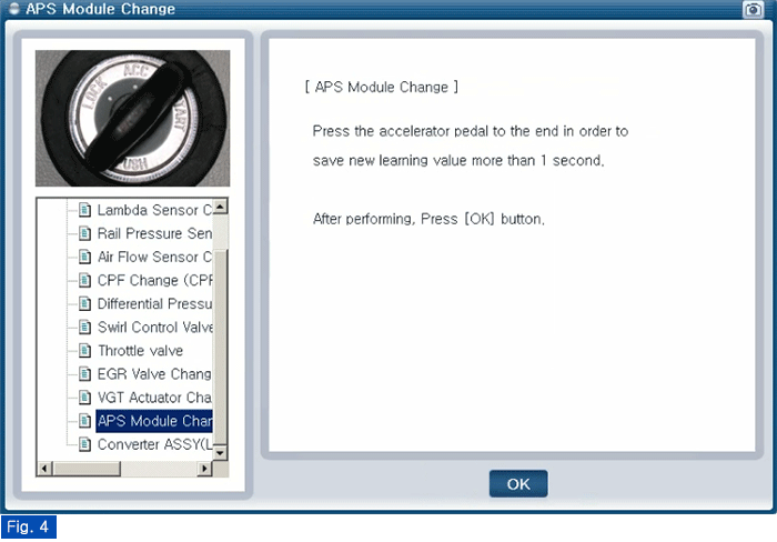
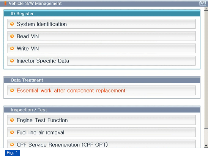
Select "APS Module Change"
Fig.1 ) Vehicle S/W Management list of Engine
Fig.2 ) "Essential Work After Component Replacement"
Fig.3) APS Module Change 1
Fig.4) APS Module Change 2
Fig.5) Complete