Inspection condition : Ignition switch "ON"
Specification :Reference frequency : Approx. 19.0 Hz / MAFS signal : Approx. 1.9 kHz
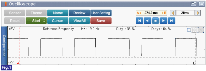
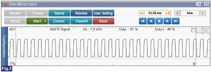
Fig. 1) MAFS reference frequency signal under Ignition switch "ON"
Fig. 2) MAFS signal under Ignition switch "ON"
Ignition Switch "OFF"
Connect VMI to GDS and set up the Oscilloscope.(2 Channel):
Channel A (+) : MAFS signal terminal (MAFS Harness Connector)
Channel A (-) : Ground
Channel B (+) : Reference frequency terminal (MAFS Harness Connector)
Channel B (-) : Ground
Ignition switch "ON" & Engine "OFF"
Inspection condition : Ignition switch "ON"
Specification :Reference frequency : Approx. 19.0 Hz / MAFS signal : Approx. 1.9 kHz


Fig. 1) MAFS reference frequency signal under Ignition switch "ON"
Fig. 2) MAFS signal under Ignition switch "ON"
Is the measured value within specification?
 | ▶ Go to "Intake Air Temperature Sensor 10. Is the measured value within specification?
caution
•
When installing component, tighten it within specification.
•
If component is dropped, check for proper operation. The internal damage may be present. caution
•
Careful not to damage the sensing element. caution
•
When EEGR is replaced, perform "Essential work after component replacement. Otherwise, vehicle performance and emission control may not work properly until auto learning is completed. Vehicle S/W Management 1. Ignition Switch "OFF" 2. Connect GDS to Data Link Connector(DLC). 3. Ignition Switch "ON" & Engine "OFF" 4. Perform "Essential Work After Component Replacement" in "Vehicle Software Management" with GDS. 5. Select "Air Flow Sensor Change" 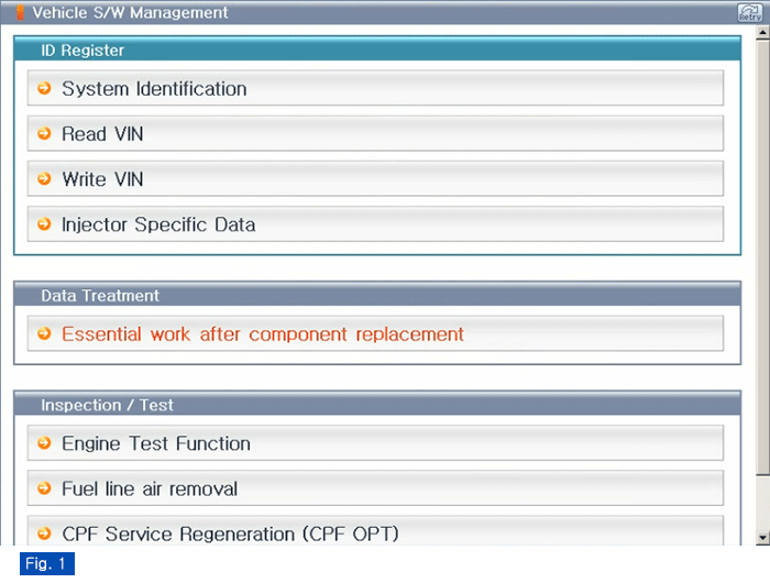 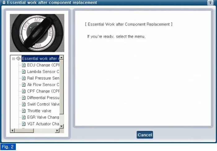 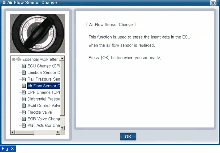  Fig.1 ) Vehicle S/W Management list of Engine Fig.2 ) "Essential Work After Component Replacement" Fig.3 ) Air Flow Sensor Change Fig.4 ) Complete |