3.
Has a problem been found?
 | ▶ Repair as necessary and go to "Verification of Vehicle Repair" procedure. |
 | ▶ Go to "Power Circuit Inspection" procedure. |
Many malfunctions in the electrical system are caused by poor harness and terminals.
Faults can also be caused by interference from other electrical systems, and mechanical or chemical damage.
Thoroughly check all connectors (and connections) for looseness, bending, corrosion, contamination, deterioration, and/or damage.
Has a problem been found?
| ▶ Repair as necessary and go to "Verification of Vehicle Repair" procedure. |
| ▶ Go to "Power Circuit Inspection" procedure. |
Ignition Switch "OFF"
Refer to "Shop Manual" and disconnect oil level sensor connector.
Ignition Switch "ON"
Measure the voltage between power terminal of oil level sensor harness connector and chassis ground.
Specification :B+
Is the measured value within specification?
| ▶ Go to "Ground Circuit Inspection" procedure. |
| ▶ Inspect and repair open or short in circuit, and then go to "Verification of Vehicle Repair" procedure. |
Ignition switch "OFF"
Disconnect battery (-) cable.
Refer to "Shop Manual" and disconnect oil level sensor connector.
Measure the resistance between ground terminal of oil level sensor harness connector and chassis ground.
Specification: Approx. below 1Ω
Ignition switch "OFF"
Refer to "Shop Manual" and disconnect oil level sensor connector.
Ignition switch "ON"
Measure the voltage between power terminal of oil level sensor harness connector and chassis ground.(A)
Measure the voltage between power terminal and ground terminal of oil level sensor harness connector.(B)
Specification :Difference in (A) and (B) is less than 200 mV
Is the measured value within specification?
| ▶ Go to "Signal Circuit Inspection" procedure. |
| ▶ Inspect and repair open or short in circuit, and then go to "Verification of Vehicle Repair" procedure. |
Ignition Switch "OFF"
Refer to "Shop Manual" and disconnect oil level sensor connector.
Connect VMI to GDS and set up the Oscilloscope.(2 Channel):
Channel A (+) : Signal terminal (Oil Level Sensor Harness Connector)
Channel A (-) : Ground
Ignition switch "ON"
Specification: Refer to figure below
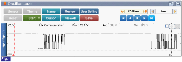
Fig.1) LIN communication signal waveform of battery sensor.
Is the measured value within specification?
| ▶ Go to "Component Inspection" procedure. |
| ▶ Inspect and repair open or short in circuit, and then go to "Verification of Vehicle Repair" procedure. |
