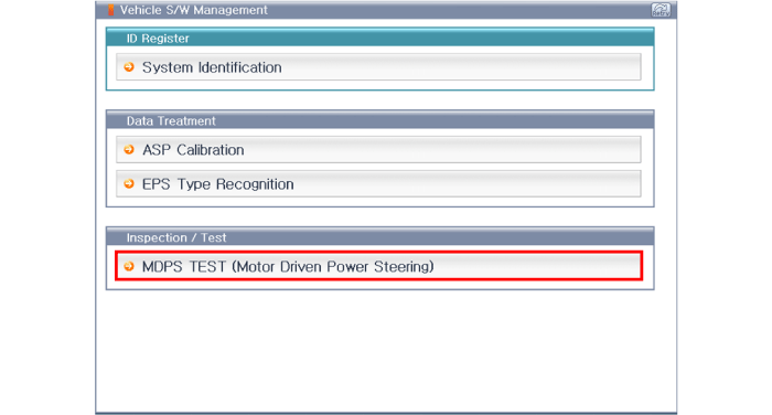
After Selecting the "vehicle model" and "system", select the "MDPS TEST" on GDS vehicle selection screen.
After or before servicing the EPS system, perform the troubleshooting and test procedure as follows. Compare the system condition with normal condition in the table below and if abnormal symptom is detected, perform necessary remedy and inspection.
Test condition | Normal condition: Motor must not supply steering assist. | ||
Symptom | Possible cause | Remedy | |
IG Off | Motor supplies steering assist. | ASP is not calibrated. | Perform the ASP calibration using a scan tool. |
IG power supplies | Inspect the IG power supply line. | ||
Test condition | Normal condition: Motor must not supply steering assist, Warning lamp is illuminated. | ||
Symptom | Possible cause | Remedy | |
IG On/Engine Off | Motor supplies steering assist. | ASP is not calibrated. | Perform the ASP calibration using a scan tool. |
EMS CAN signal is not received. | Inspect the CAN line. | ||
Warning lamp is not illuminated. | Cluster fault | Inspect the cluster and cluster harness | |
Test condition | Normal condition: Motor supplies steering assist, Warning lamp is not illuminated. | ||
Symptom | Possible cause | Remedy | |
IG On/Engine On | Warning lamp is illuminated and Motor dose not supply steering assist. | EPS (Hot at all times) and IG power supply fault | Inspect the connector and harness for EPS (Hot at all times) and IG power supply line. |
DTC is detected by system. | Perform the self test using a scan tool and repair or replace. | ||
Warning lamp is illuminated and Motor supplies steering assist. | ASP is not calibrated. | Perform the ASP calibration using a scan tool. | |
CAN communication between EPS and cluster is fault. | Inspect the CAN line. | ||
ASP: Absolute Steering Position
CAN: Controller Area Network
EMS: Engine Management System
The following symptoms may occur during normal vehicle operation and if there is no EPS warning light illumination, it is not malfunction of EPS system.
After turning the ignition switch on, the steering wheel becomes heavier while it performs EPS system diagnostics, for about 2 seconds, then it becomes normal steering condition.
After turning the ignition switch on or off, EPS relay noise may occur but it is normal.
When it is steered, while the vehicle is stopped or in low driving speed, motor noise may occur but it is normal operating one.
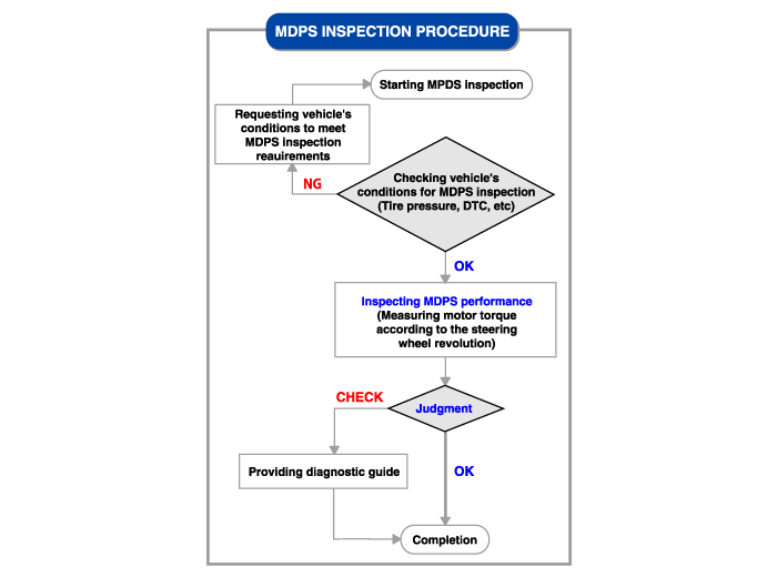
This bulletin provides Motor Driven Power Steering (MDPS) diagnostic procedure using GDS to diagnose theheavy steering effort, abnormal position of steering parts and MIL illumination in steering system.
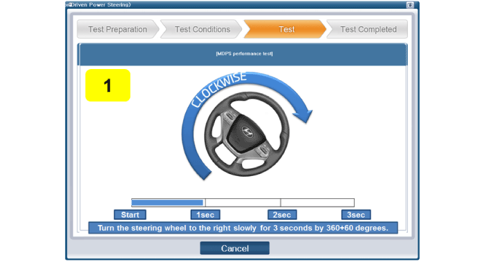
GDS judges the MDPS normal/abnormal state by calculating the MDPS motor torque generated when turning the steering wheel to left and right at 360˚ per 3 seconds.
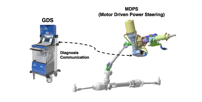
Connect self-diagnosis connector(16pins) located in the lower of driver side crash pad to self-diagnosis device.
Turn the self-diagnosis device after key is ON.
After Selecting the "vehicle model" and "system", select the "MDPS TEST" on GDS vehicle selection screen.

Prepare a vehicle according to the required vehicle’s conditions.
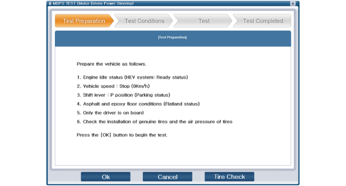
Search the DTCs relevant to the MDPS and then erase them if found.
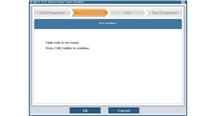
Perform the MDPS TEST.
If the results of MDPS performance inspection are “OK”, click “OK” and then finish the service work.
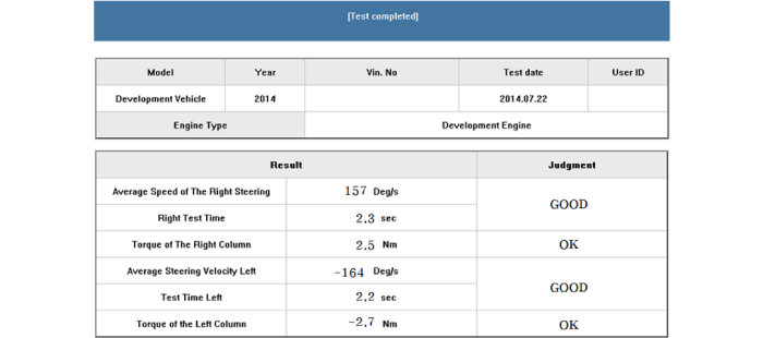
If the results of MDPS inspection are “Check”, click “Inspection” and then inspect below items.
EPS Warning light illuminated
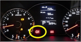
Inspect DTCs relevant to the steering system.
DTC | ||
C1112 | EPS Warning light illuminated | Conduct repair according to the DTC diagnostic guide. |
C1290 | ||
C1604 | ||
C1704 | ||
C1705 | ||
C2400 | ||
C2401 | ||
C2412 | ||
C2413 |
Vibration and Noise
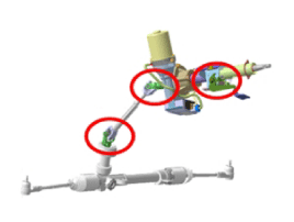
Inspect MDPS portions where are mounted to the body. (Checking tightening conditions of bolts and nuts)
Inspect universal joint mounting bolts.
Inspection for heavy steering effort
Inspect tire pressure and width.
Check that the heavy steering effort occurs or not when vehicle speed is not received.
Check DTCs relevant to the CAN communication error.
DTC | ||
C1611 | DTCs relevant to the CAN communication | Conduct diagnosis if DTCs do not recur after erasing DTCs |
C1616 | ||
C1622 | ||
C1692 | ||
C1628 | ||
C1693 | Inspect CAN line if DTCs recur after erasing DTCs. | |
C1614 | ||
C1696 | ||
C1697 | ||
C1812 | ||
C1817 |
Other DTC judgment
DTC | ||
C1102 | Low voltageof battery | Conduct diagnosis after inspecting battery. |
C1109 | ||
C1261 | Setting steering angle to zero point | Reset steering angle to zero point |
C1603 | Overheated | Conduct retest after cooling MDPS motor. |
Check if the battery is fully charged before ASP calibration or EPS type recognition.
Be careful not to disconnect any cables connected to the vehicle or scan tool during ASP calibration or EPS type recognition.
When the ASP calibration or EPS type recognition is completed, turn the ignition switch off and wait for several seconds, then start the engine to confirm normal operation of the vehicle.
Connect self-diagnosis connector(16pins) located in the lower of driver side crash pad to self-diagnosis device.
Turn the self-diagnosis device after key is ON.
After Selecting the "vehicle model" and "system", select the "ASP Calibration" on GDS vehicle selection screen.
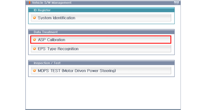
Connect self-diagnosis connector(16pins) located in the lower of driver side crash pad to self-diagnosis device.
Turn the self-diagnosis device after key is ON.
After Selecting the "vehicle model" and "system", select the "EPS Type Recognition" on GDS vehicle selection screen.
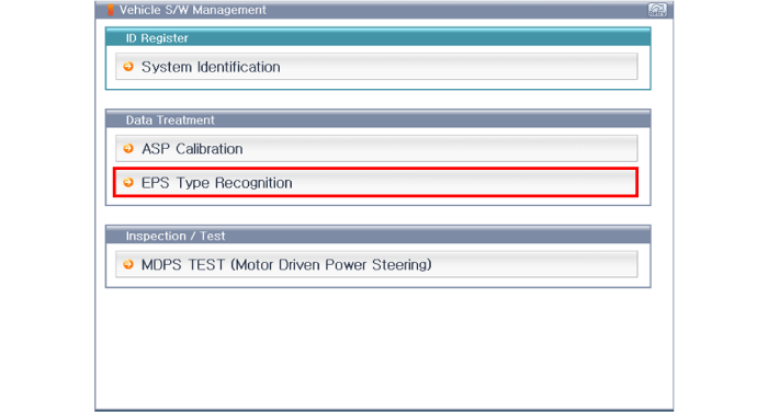
This is guidance about diagnostic procedures by using diagnostic equipment , the main contents are as follows:
Connect the diagnostic equipment to self-diagnosis connector in lower of driver's side crash pad, and then turn on the diagnostic equipment after ignition key is ON.
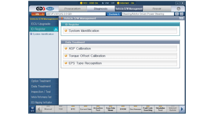
After select "vehicle model" and "EPS" on the GDS screen, select confirmation button.
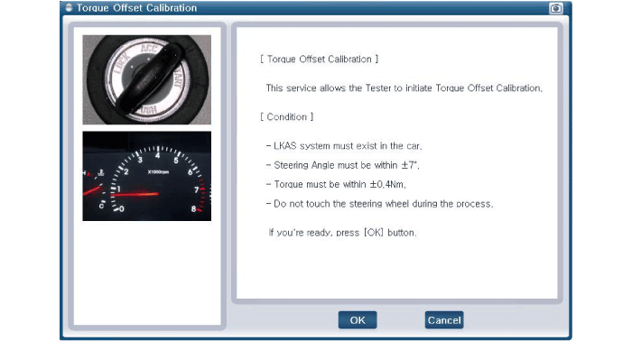
After completing steering wheel alignment adjustment, idling condition should be at the 0 °position so that the hysteresis is not applied to the steering wheel.
Steering wheel angle is only available within ± 7 °.
Torque sensor should be at below ± 0.4Nm.
In NG screen, retry after adjusting steering wheel angle/torque value.
Do not touch the steering wheel during torque sensor calibration.
Save/manage the torque calibration sensor operation conditions(steering wheel angle and the torque value data)
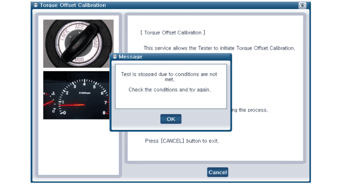
- Vehicle S/W Management
- Torque Offset Calibration_entry
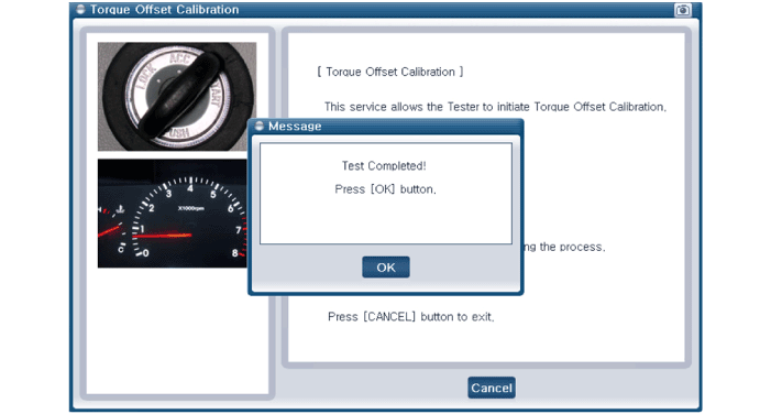
- Torque Offset Calibration_success
- Torque offset calibration_failure
