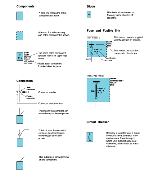
Schematic diagrams
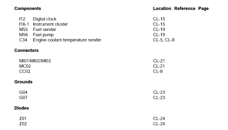
Component location indexes
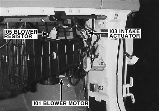
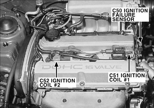
Component locations
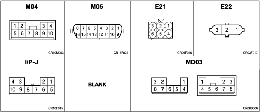
Connector configurations
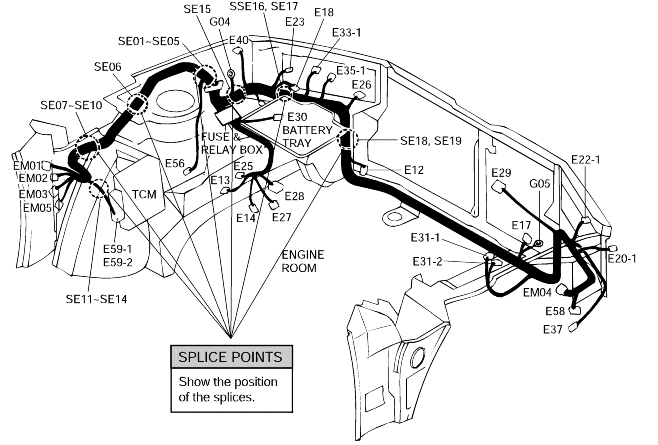
Harness layouts
 |  |
Female | Male | Remarks | |
Actual Illustration |  |  | It is not the shape of the connector housing, but the connector pin that distinguishes between male or female connectors. When numbering female and male connectors, refer to the numbering order in the following table. Some connectors may not follow this method of numbering order. For individual detailed numbering, refer to the CONNECTOR CONFIGURATIONS. |
Illustration in the Shop manual |  |  |
UNLESS OTHERISE STATED, ALL CONNECTOR VIEWS ARE FROM THE TERMINAL SIDE OF THE CONNECTOR.
Numbering order | Remarks | |
Female Connector |  | Numbered in order from upper right to lower left |
Male Connector |  | Numbered in order from upper left to lower right |
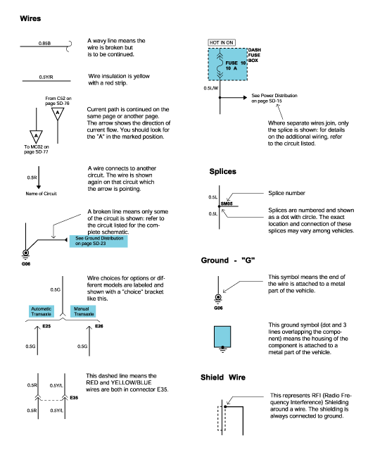
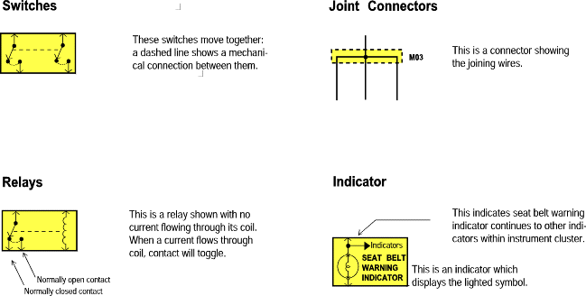
Symbol | Color of wire | Symbol | Color of wire | |
B | Black | O | Orange | |
Br | Brown | P | Pink | |
G | Green | Pp | Purple | |
Gr | Gray | R | Red | |
L | Blue | T | Tan | |
Lg | Light green | W | White | |
Ll | Light blue | Y | Yellow |
Harness name | Location | Symbol |
Engine harness | Engine compartment | E |
Main, Floor, Roof, Seat, Steering harness | Passenger compartment | M |
Control, Injector ext., Ignition coil harness | Engine compartment | C |
Rear harness (Trunk lid & Trunk room) | Rear and Trunk lid | R |
Instrument, Air bag, Glove box ext harness | Under crash pad and Floor | I |
Door harness | Door | D |

Connectors which connect each wiring harness are represented by the following symbols.


Verify the customer's complaints
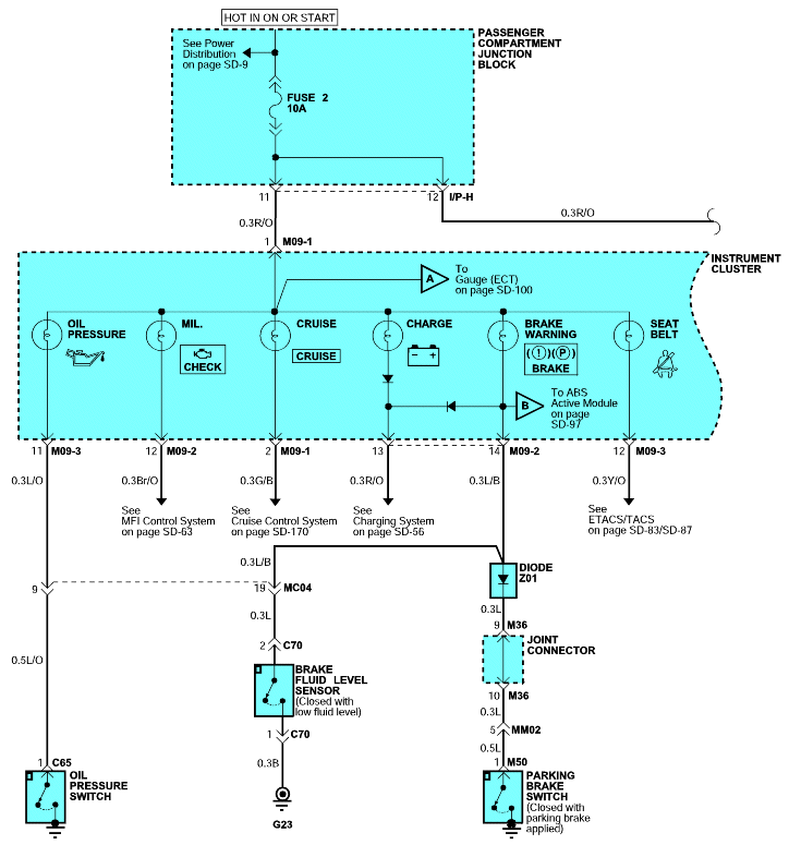
Read and analyze the schematic diagram
Inspect the circuit/ component with the problem isolated
Repair the problem
Make sure the circuit works
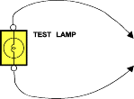
A number of circuits include solid-state modules, such as the Engine Control Module (ECM), used with computer command control injection. Voltage in these circuits should be tested only with a 10-megaohm or higher impedance digital voltmeter. Never use a test lamp on circuits that contain solid-state modules. Damage to the modules may result.
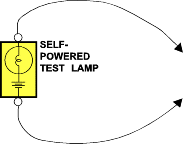
Never use a self-powered test lamp on circuits that contain solid state modules. Damage to these modules may result.
Do not use a fuse with a higher rating than the specified fuse that protects the circult being tested. Do not use this tool in any situation to substitute an input or output at the solid-statecontrol module, such as ECM, TCM, etc.
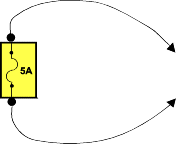
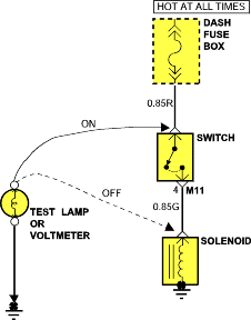
Connect one lead of a test lamp or voltmeter to a ground. If you are using a voltmeter, be sure it is the voltmeter's negative test lead youhave connected to ground.
Connect the other lead of the test lamp or voltmeter to a selected test point (connector or terminal).
If the test lamp glows, there is voltage present. If you are using a voltmeter, note the voltage reading. Aloss of more than 1 volt from specificationindicates a problem.
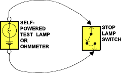
Disconnect the battery negative terminal.
Connect one lead of a self-powered test lamp or ohmmeter to one end of the part of the circuit you wish to test. If you are using an ohmmeter,hold the leads together and adjust the ohmmeter to read zero ohms.
Connect the other lead to the other end.
If the self-power test lamp glows, there is continuity. If you are using an ohmmeter, low or zero resistance means good continuity.
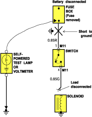
Disconnect the battery negative terminal.
Connect one lead of a self-powered test lamp or an ohmmeter to the fuse terminal on the load side.
Connect the other lead to a ground.
Beginning near the fuse block move the harness from side to side. Continue this proceedure (about six inches apart) while watching the self-poweredtest lamp or ohmmeter.
When the self-powered test lamp glows, or ohmmeter registers, there is a short to a ground in the wiring near that point.
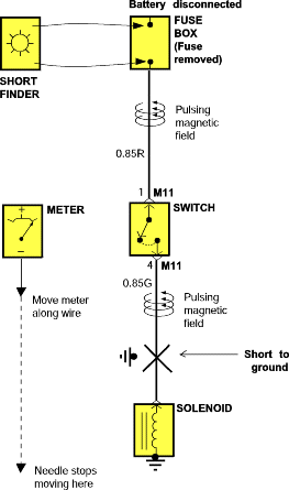
Remove the blown fuse. Leave the battery connected.
Connect the short finder across the fuse terminals.
Close all switches in series in the circuit that is being testing.
Turn on the short circuit locator. It sends pulses of current to the short. This creates a pulsing magnetic field around the wiring betweenthe fuse box and the short.
Beginning at the fuse box, slowly move the short finder along the circuit wiring. The meter will show current pulses through sheet metal and body trim. As long as the meter is between the fuse and the short, the needle will move with each current pulse. Once the meter is moved past the point of the short, the needle will stop moving. Check around this area tolocate the cause of the short circuit.
