Disconnect the Hi-Scan (Pro).
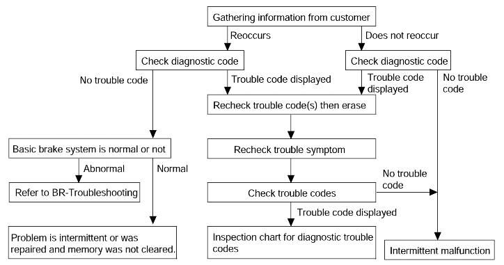
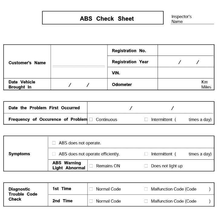
* Using the customer problem analysis check sheet for reference, ask the customer as much detail as possible about the problem. |
Phenomenon | Explanation |
System check sound | |
ABS operation sound | 1. Sound of the motor inside the ABS hydraulic unit operation (whine). 2. Sound is generated along with vibration of the brake pedal (scraping). 3. When ABS operates, sound is generated from the vehicle chassis due to repeated brake application and release (Thump : suspension; squeak: tires) |
ABS operation (Long braking distance) | For road surfaces such as snow-covered and gravel roads, the braking distance for vehicles with ABS can sometimes be longer than that for other vehicles. Accordingly, advise the customer to drive safely on such roads bylowering the vehicle speed. |
Pedal kick back | Pedal kick back is normal operation. |
Diagnosis detection conditions can vary depending on the diagnosis code. When checking the trouble symptom after the diagnosis code has been erased,ensure that the requirements listed in "Comment" are met. | |
Turn the ignition OFF.
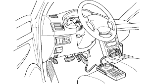
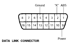
Connect the Hi-Scan (Pro) to the Data Link Connector located underneath the lower crash pad panel.
Turn the ignition ON.
Use the Hi-Scan (Pro) to check for diagnostic trouble codes.
After completion of the repair or correction of the problem, erase the stored fault codes using the clear key on the Hi-Scan (Pro).
Disconnect the Hi-Scan (Pro).


No. | Description | Recognition | Remark |
01 | Motor | Motor pump relay operation (Click sounds) | Actuation time is limited to MAX. 2 seconds |
02 | Front left valve (In) | Front left solenoid valve operation (Click sounds) | |
03 | Front right valve (In) | Front right solenoid valve operation (Click sounds) | |
04 | Rear left valve (In) | Rear left solenoid valve operation (Click sounds) | |
05 | Rear right valve (In) | Rear right solenoid valve operation (Click sounds) | |
06 | Front left valve (Out) | Front left solenoid valve operation (Click sounds) | |
07 | Front right valve (Out) | Front right solenoid valve operation (Click sounds) | |
08 | Rear left valve (Out) | Rear left solenoid valve operation (Click sounds) | |
09 | Rear right valve (Out) | Rear right solenoid valve operation (Click sounds) |
No. | Description | Recognition | Remark |
01 | TC FL valve | Front left traction control valve operation | |
02 | TC FR valve | Front right traction control valve operation |
No. | Description | Recognition | Remark |
01 | FL wheel speed SNSR | Front left wheel speed sensor | Minimum level is V� ≥ 10 km/h |
02 | FR wheel speed SNSR | Front right wheel speed sensor | |
03 | RL wheel speed SNSR | Rear left wheel speed sensor | |
04 | RR wheel speed SNSR | Rear right wheel speed sensor | |
05 | ABS SRI status | Warning lamp | |
06 | Brake SW | Brake switch | |
07 | Motor pump relay | Motor relay | |
08 | Valve relay | Valve relay | |
09 | Motor pump status | Motor | |
10 | FL valve (In) | Front left valve (In) | |
11 | FR valve (In) | Front right valve (In) | |
12 | RL valve (In) | Rear left valve (In) | |
13 | RR valve (In) | Rear right valve (In) | |
14 | FL valve (Out) | Front left valve (Out) | |
15 | FR valve (Out) | Front right valve (Out) | |
16 | RL valve (Out) | Rear left valve (Out) | |
17 | RR valve (Out) | Rear right valve (Out) |
No. | Description | Recognition | Remark |
01 | FL wheel speed SNSR | Front left wheel speed sensor | |
02 | FR wheel speed SNSR | Front right wheel speed sensor | |
03 | RL wheel speed SNSR | Rear left wheel speed sensor | |
04 | RR wheel speed SNSR | Rear right wheel speed sensor | |
05 | TCS switch | TCS swtich | |
06 | FL TC valve (Out) | Front left traction control valve (Out) | |
07 | FR TC valve (Out) | Front right traction control valve (Out) |
Trouble system | Inspection procedure No. | |
Communication with Hi-Scan (Pro) is not possible | Communication with any system is not possible. | 1 |
Communication with ABS only is not possible. | 2 | |
When the ignition key is turned to "ON" (engine OFF), the ABS warning lamp does not illuminate. | 3 | |
After the engine starts, the lamp remains illuminated. | 4 | |
Faulty ABS operation | Unequal braking power on both sides | 5 |
Insufficient braking power | ||
ABS operates under normal braking conditions | ||
ABS operates before vehicle stops under normal braking conditions | ||
Large brake pedal vibration (See Caution) | - | |
During ABS operation, the brake pedal may vibrate or may not be able to be depressed. Such phenomena are due to intermittent changes in hydraulic pressure inside the brake line to prevent the wheels from locking and is notan abnormality.
Communication with Hi-Scan (Pro) is not possible. (Communication with all systems is not possible.) | Probable cause |
Possible defect in the power supply system (including ground) for the diagnosis line. | ● Malfunction of connector. ● Malfunction of wiring harness. |
Communication with Hi-Scan (Pro) is not possible. (Communication with ABS only is not possible.) | Probable cause |
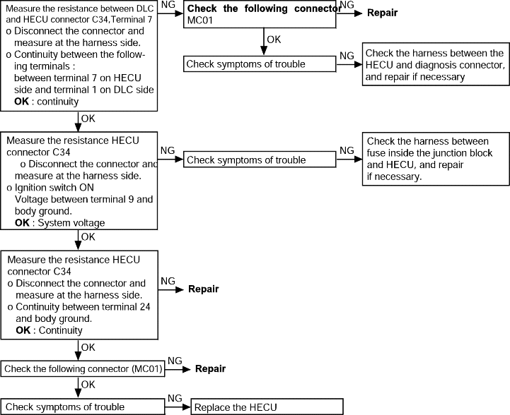
When communication with Hi-Scan (Pro) is not possible, the cause may be probably an open circuit in the HECU powercircuit or an open circuit in the diagnosis output circuit. | ● Blown fuse. ● Malfunction of wiring harness or connector. ● Malfunction of HECU. |
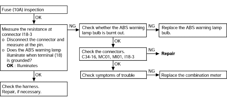
When ignition key is turned "ON" (engine OFF), the ABS warning lamp does not illuminate | Probable cause |
When current flows in the HECU, the ABS relay turns from on to off as the initial check. The ABS warning lamp will illuminate when the ABS relay is off even if there is a problem withthe circuit between the ABS warning lamp and the HECU. Therefore, if the lamp does not illuminate, the cause may be an open circuit in the lamp power supply circuit, a blown bulb, an open circuit in both the circuits between the ABS warning lamp and the HECU, and in the circuitbetween the ABS warning lamp and the ABS relay. | ● Blown fuse. ● Burnt out ABS warning lamp bulb. ● Malfunction of wiring harness or connector. |
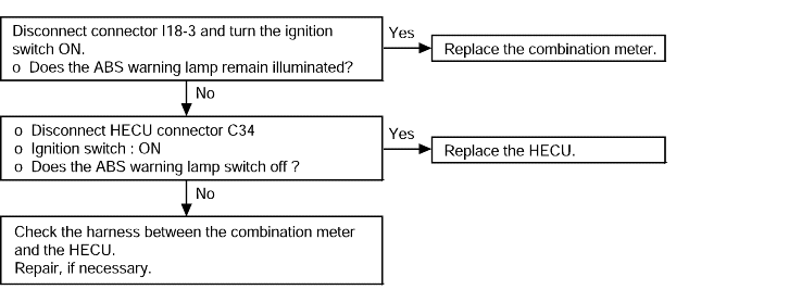
Even after the engine is started, the ABS warning lamp remains illuminated | Probable cause |
A possible short-circuit in the ABS warning lamp illumination circuit | ● Malfunction of combination meter. ● Malfunction of HECU. ● Malfunction of wiring harness. |
This trouble symptom is limited to cases where communication with the Hi-Scan (Pro) is possible (HECU power supply is normal) and DTC isnormal.
Brake operation is abnormal | Probable cause | |
Brake operation varies depending on driving conditions and road surface conditions, so diagnosis can be difficult. However, if a normal DTC is displayed, carry out the following inspection. | ● Improper installation of wheel speed sensor. ● Incorrect sensor harness contact. ● Foreign material on wheel speed sensor. | ● Malfunction of wheel speed sensor. ● Malfunction of rotor. ● Malfunction of wheel bearing. ● Malfunction of HECU. |
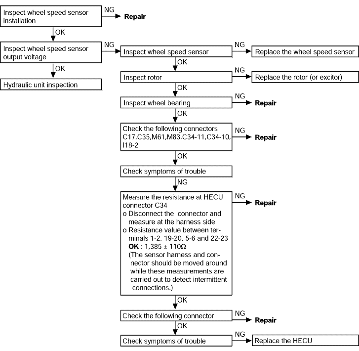
DTC on Scan tool | Description | MIL* | Memory | |
C1103 | Voltage out of range (Under and over voltage) | O | O | |
C1200 | FL wheel sensor : | Open or short to GND | O | O |
C1201 | FL wheel sensor : | Speed jump or wrong exciter | O | O |
C1202 | FL wheel sensor : | Air-gap error | O | O |
C1203 | FR wheel sensor : | Open or short to GND | O | O |
C1204 | FR wheel sensor : | Speed jump or wrong exciter | O | O |
C1205 | FR wheel sensor : | Air-gap error | O | O |
C1206 | RL wheel sensor : | Open or short to GND | O | O |
C1207 | RL wheel sensor : | Speed jump or wrong exciter | O | O |
C1208 | RL wheel sensor : | Air-gap error | O | O |
C1209 | RR wheel sensor : | open or short to GND | O | O |
C1210 | RR wheel sensor : | Speed jump or wrong exciter | O | O |
C1211 | RR wheel sensor : | Air-gap error | O | O |
C1503 | TCS switch error | O | O | |
C1604 | ECU hardware error | O | O | |
C1605 | CAN hardware error | Δ | O | |
C1610 | CAN bus off error | Δ | O | |
C1611 | CAN timeout EMS | Δ | O | |
C1612 | CAN timeout TCU | Δ | O | |
C1613 | CAN transmission unmatching | Δ | O | |
C1700 | Parameter error | O | O | |
C2112 | Main relay, fuse | O | O | |
C2114 | Disturbance (Including valve failure) | O | O | |
C2402 | Motor pump | O | O | |
*MIL : Malfunction Indication Lamp
O : ABS warning lamp
Δ : TCS warning lamp
DTC No. C1200, C1203, C1206, C1209 Wheel speed sensor open or short to GND circuit | Probable cause |
The HECU determines that an open or short circuit has occured in more than one wire of a wheel speed sensor. | ● Malfunction of wheel speed sensor. ● Malfunction of wiring harness or connector. ● Malfunction of HECU. |
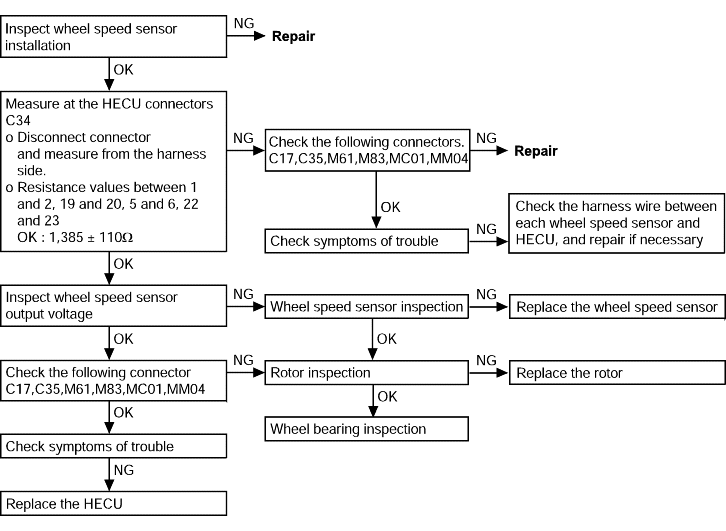
DTC No. C1201, C1204, C1207, C1210 (Speed jump or wrong exciter) | Probable cause |
Abnormal output signal from a wheel speed sensor other than an open or short circuit. | ● Improper installation of wheel speed sensor. ● Malfunction of wheel speed sensor. ● Malfunction of rotor. ● Malfunction of wheel bearing. ● Malfunction of wiring harness or connector. ● Malfunction of HECU. |
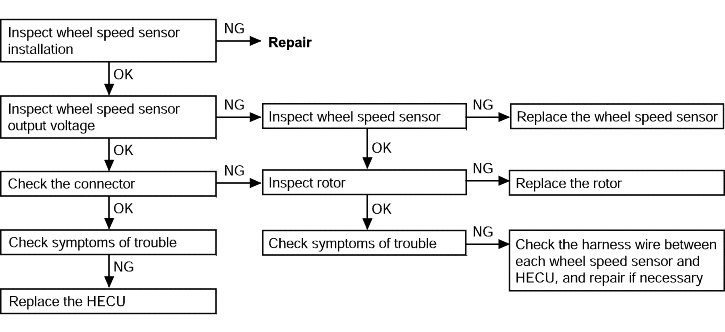
DTC No. C1202, C1205, C1208, C1211 (Large air gap) | Probable cause |
No wheel speed sensor output signal. | ● Malfunction of wheel speed sensor. ● Improper installation of wheel speed sensor. ● Malfunction of rotor (excitor). ● Malfunction of wiring harness or connector. ● Malfunction of HECU. |
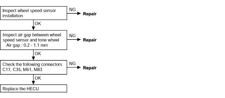
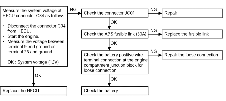
DTC No. C1103 Voltage out of range (Under or over voltage) | Probable cause |
The voltage of the HECU power supply drops lower or rises higher than the specified value. If the voltage returnsto the specified value, this code is no longer output. | ● Malfunction of wiring harness or connector. ● Loose connection of the positive battery terminal wire at the engine compartment junction block. ● Malfunction of HECU. |
caution If the battery voltage drops or rises during inspection, the DTC C1103 will be output as well. If the voltage returns to the standard value, this code is no longer output. Therefore, before carryingout the following inspection, make sure the battery is fully charged. |
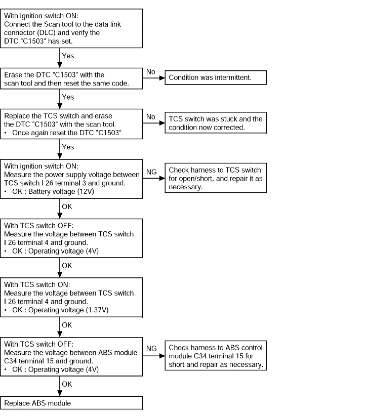
DTC No. C1503 TCS switch error | Probable cause |
TCS switch line open or short. | ● Malfunction of TCS switch. ● Malfunction of wiring harness. ● Malfunction of HECU. |
DTC No. C1604 HECU Hardware (EEPROM and ECU failure) | Probable cause |
The HECU always monitors the solenoid valve drive circuit. It determines that there is an open or short-circuit in the solenoid coil or in a harness even if no current flows in the solenoidor through the HECU. | ● Malfunction of wiring harness. ● Malfunction of HECU. |
DTC No. C2112 Valve relay (Including fuse failure) | Probable cause |
When the ignition switch is turned ON, the HECU switches the valve relay on and off during its initial check. During this time, voltage sent to the valve relay is compared to the voltage in the valve power monitor line. If no current is detected in the valve power monitor line, the HECU determines that there is an open circuit and DTC C2112is recorded. | ● Malfunction of wiring harness or connector. ● Malfunction of HECU. |

DTC No. C1605 CAN hardware error DTC No. C1700 Parameter error DTC No. C2114 Disturbance | Probable cause |
Replace the HECU. | ● Interference by means of electronic wave. ● Mismatching of the calculation between main and sub processor. ● Defects of the valve coil and valve coil operating circuit element. |
DTC No. C1611 CAN timeout EMS DTC No. C1612 CAN timeout TCU, DTC No. C1613 CAN wrong matched transmission | Probable cause |
Inspect the EMS or TCU according to the instructions of Engine or T/M group. | ● No message from EMS or TCU for 500ms. ● Message from A/T or M/T signal mismatch the message from ECM or TCU. |
DTC No. C1610 CAN bus off error | Probable cause |
Check CAN bus wiring. Check the connectors C34 and C44-3. | ● CAN bus cable open or short to ground or battery. |
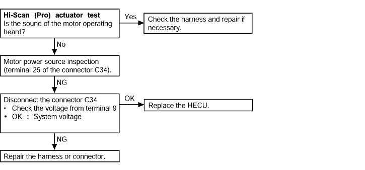
DTC No. C2402 motor pump failure (Motor relay, motor) | Probable cause |
When the motor power line is normal but no signal is in detected in the motor monitor line. | ● Malfunction of wiring harness. ● Malfunction of HECU. |
caution Powering the motor with the Hi-Scan (Pro) will discharge the battery. Start and run the engine for a while after testingis complete. |
