
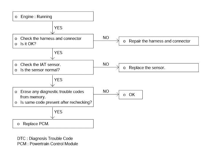
When the intake air temperature is detected as below -40°C or higher than 120°C
Input signal from intake air temperature sensor is below 0.1V or above 4.8V when engine is in a full warm-up condition.
Check item | Data display | Check conditions | Intake air temperature | Test specification |
Intake air temperature sensor | Air temperature | Ignition switch : ON or engine running | When -20°C (-4°F) | -20°C |
When 0°C (32°F) | 0°C | |||
When 20°C (68°F) | 20°C | |||
When 40°C (104°F) | 40°C | |||
When 80°C (176°F) | 80°C |
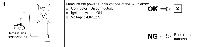
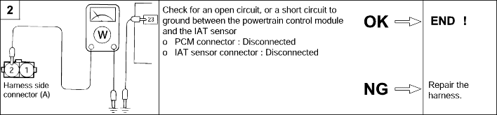
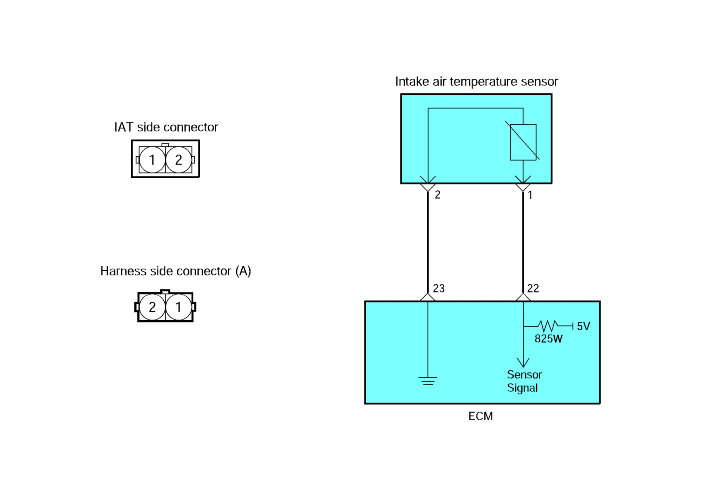
Use the multimeter, measure the sensor resistance.
Measure the resistance between the IAT sensor terminal 1 and 2.
IG.SW. ON | Temperature °C (°F) | Resistance (kΩ) |
-40 (-40) | 33.85 ~ 61.20 | |
-10 (-14) | 6.90 ~ 11.50 | |
20 (68) | 2.22 ~ 2.82 | |
80 (176) | 0.30 ~ 0.36 |
If the resistance deviates from the standard value, replace the intake air temperature sensor assembly.