DTC | Diagnostic item |
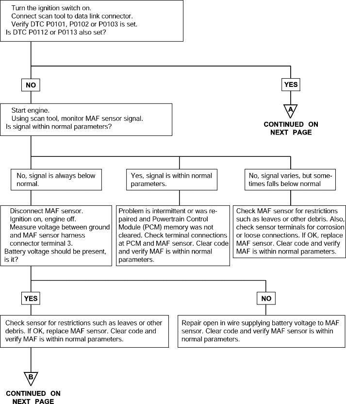
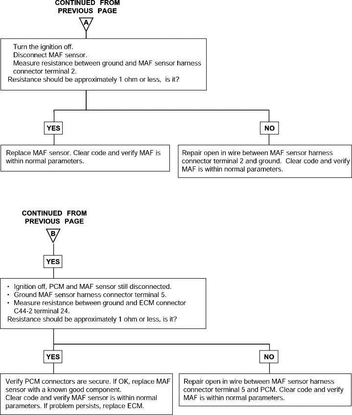
P0101 P0102 P0103 | Mass Air Flow Circuit Rang/Performance Problem Mass Air Flow Circuit Low Voltage Mass Air Flow Circuit High Voltage |
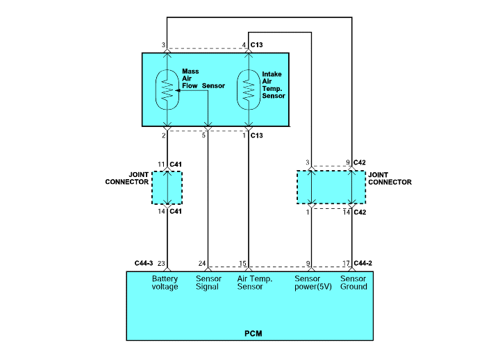
The Mass Air Flow (MAF) sensor is located near the air cleaner.
The sensor measures the mass of air passing through the air intake and generates a voltage signal. The Powertrain Control Module(PCM) receives the voltage generated by the sensor and uses the signal to set fuel injector basepulse width and ignition timing.
The resistance of the sensor decreases as mass air flow increases. Voltage and current flow is increased to maintain the film's temperature and resistivity.
DTC detection condition | Probable cause |
Background ● While the engine is running, the mass air flow sensor outputs a voltage signal which corresponds to the mass of air flow. ● The Powertrain Control Module checks whether the voltage of this signal is at or above the set value. Check Area ● At idle rpm ● Or engine speed is 3000 r/min or more Judgment Criteria ● Sensor output voltage has continued to be 0.5V or lower for 4 sec. Check Area ● Throttle position sensor voltage is 12V or lower. ● Engine speed is 2000 rpm or less. Judgment Criteria ● Sensor output voltage has continued to be 4.5V or higher for 4 seconds. | ● Mass air flow sensor failed ● Open or shorted mass air flow sensor circuit, or loose connector ● Powertrain control module failed |
DTC | Diagnostic item |
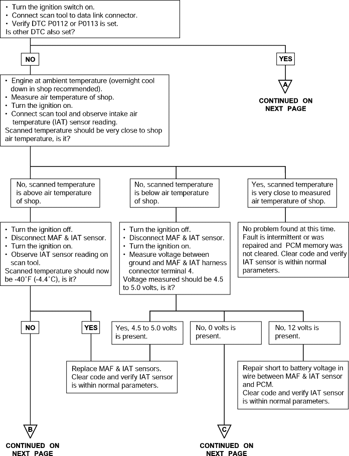
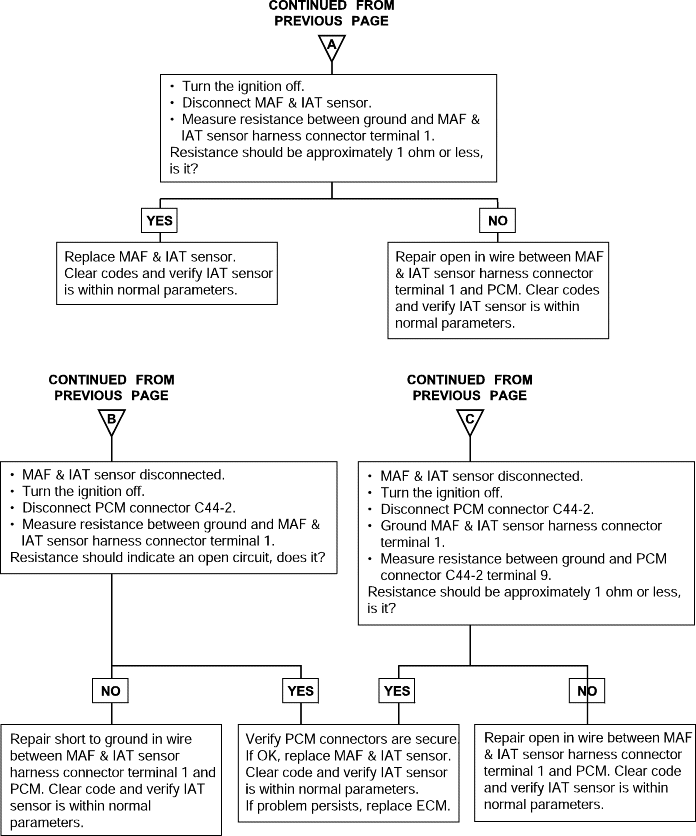
P0112 P0113 | Intake Air temperature Circuit Low Voltage Intake Air temperature Circuit High Voltage |
The Intake Air Temperature (IAT) sensor is in the MAF sensor. The IAT sensor is a variable resistor whose resistance changes as the temperature of the air flowing through the air intake changes. The Powertrain Control Module (PCM) uses the IAT sensor input to adjust fuel injector pulse width. When the temperature sensed is cold, the PCM enriches fuel mixture by increasing injector pulse width; as the air warms, the injector pulse width time is shortened.
DTC detection condition | Probable cause |
Background ● The intake air temperature sensor converts the intake air temperature to a voltage and outputs it. ● The powertrain control module checks whether the voltage is within a specified range. Check Area ● Sixty seconds or more have passed since the engine was started. Judgment Criteria ● Sensor output voltage has continued to be 4.6V or higher [corresponding to an intake air temperature of -45°C (-49°F) or lower] for 4 sec. ● Sensor output voltage has continued to be 0.2V or lower [corresponding to an intake air temperature of 125°C (257°F) or higher] for 4 sec. | ● IAT sensor failed ● Open or shorted mass air flow sensor circuit, or loose connector ● powertrain control module failed |

DTC | Diagnostic item |
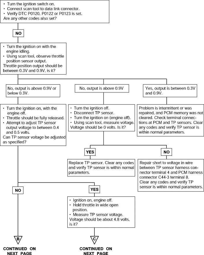
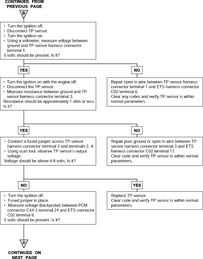
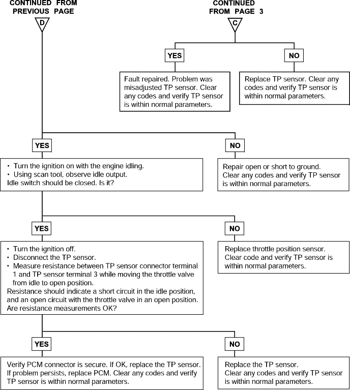
P0120 P0121 P0122 P0123 | Throttle Position Circuit Malfunction Throttle Position Sensor(SUB) Rationality Throttle Position Circuit Low Voltage Throttle Position Circuit High Voltage |
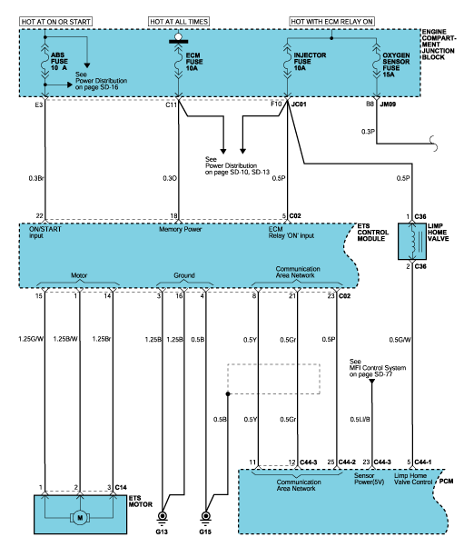
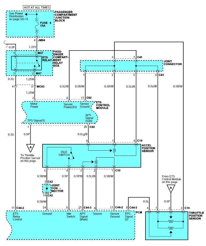
The throttle position sensor (TPS) mounts on the side of the throttle body and is connected to the throttle blade shaft. The TPS is a variable resistor (potentiometer) whose resistance changes according to the throttle blade shaft position. During acceleration, the TPS resistance decreases; during deceleration, the TPS resistance increases. The TPS also includes an idle position switch. The switch is closed in the idle position. The Powertrain Control Module (PCM) applies a reference voltage to the TPS and then measures the voltage that is present on the TPS signal circuit. The PCM uses the TPS signal to adjust the timing and injector pulse width. The TPS signal along with the MAP sensorsignal is used by the PCM to calculate the engine load.
DTC detection condition | Probable cause |
Background ● The Throttle Position sensor outputs a voltage which is proportional to the throttle valve opening angle. ● The Powertrain Control Module checks whether the voltage output by the throttle position sensor is within a specified range. In addition, it checks that the voltage output does not become too large while the engine is idling. Malfunction; out-of-range ● With the close Throttle Position switch set to ON, the sensor output voltage has continued to be 2V or higher for 4 sec. ● Sensor output voltage has continued to be 0.2V or lower for 4 sec. Operating parameters ● Engine speed is between 500 and 3,000 rpm. ● Engine load is lower than 30%. Proper Performance ● Sensor output voltage has continued to be 4.6V or higher for 4 sec. | ● Throttle Position sensor failed or maladjusted. ● Open or shorted Throttle Position sensor circuit, or loose connector. ● Closed Throttle Position switch ON malfunction. ● Closed Throttle Position switch signal wire shorted. ● Powertrain control module failed. |
DTC | Diagnostic item |
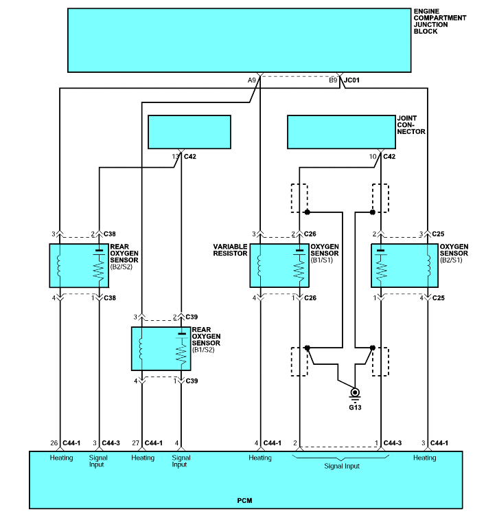
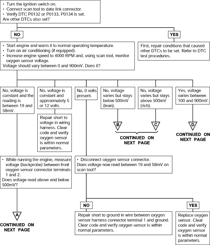
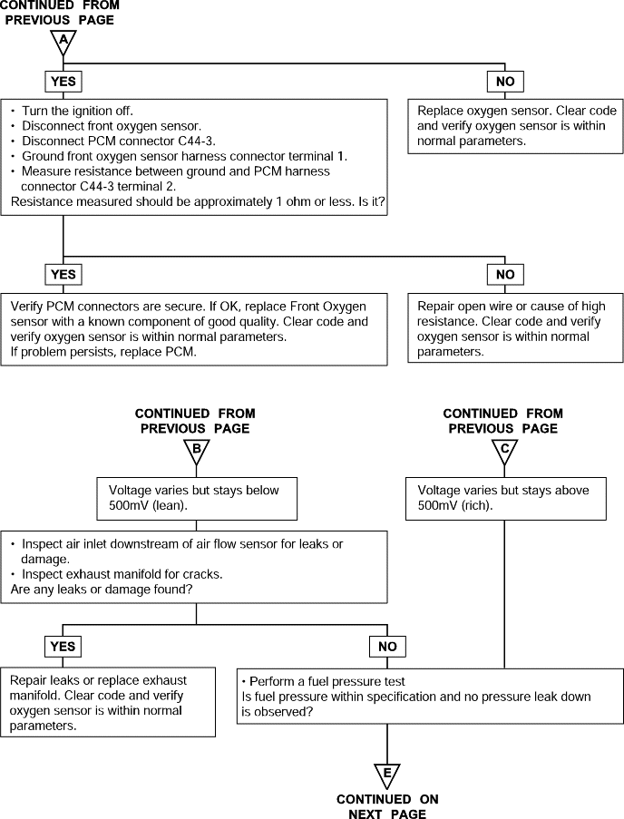
P0132 P0133 P0154 P0134 | Oxygen Sensor Circuit Malfunction (Open) Oxygen Sensor Circuit Malfunction (Bank 1, Sensor 1) Oxygen Sensor Circuit Malfunction (Bank 2, Sensor 1) Oxygen Sensor Circuit Malfunction (No Activity) |
To obtain a high purification rate for the CO, HC and NOx components of the exhaust gas, a three way catalytic converter is used, but for the most efficient use of the three-way catalytic converter, the ratio of the air must be precisely controlled so that it is always close to the stoichiometric air-fuel ratio. The oxygen sensor has the characteristic whereby its output voltage changes suddenly in the vicinity of the stoichiometric air-fuel ratio. This characteristic is used to detect the oxygen concentration in the exhaust gas and provide feedback to the computer for control of the air-fuel ratio. When the air-fuel ratio becomes LEAN, the oxygen concentration in the exhaust increases and the oxygen sensor informs the PCM of the LEAN condition. When the air-fuel ratio is RICHER than the stoichiometric air-fuel ratio the oxygen concentration in the exhaust gas is reduced and the oxygen sensor informs the PCM of theRICH condition.
The PCM determines by the electromotive force from the oxygen sensor whether the air-fuel ratio is RICH or LEAN and controls the injection time accordingly. However, if malfunction of the oxygen sensor causes output of abnormal electromotive force, the PCM is unable to perform an accurate air-fuel ratio control. The heated oxygen sensors include a heater which heats the sensing element. The heater is controlled by the PCM. When the intake air volume is low (the temperature of the exhaust gas is low), current flows to the heater to heat the sensor for accurate oxygen concentration detection.
DTC detection condition | Probable cause |
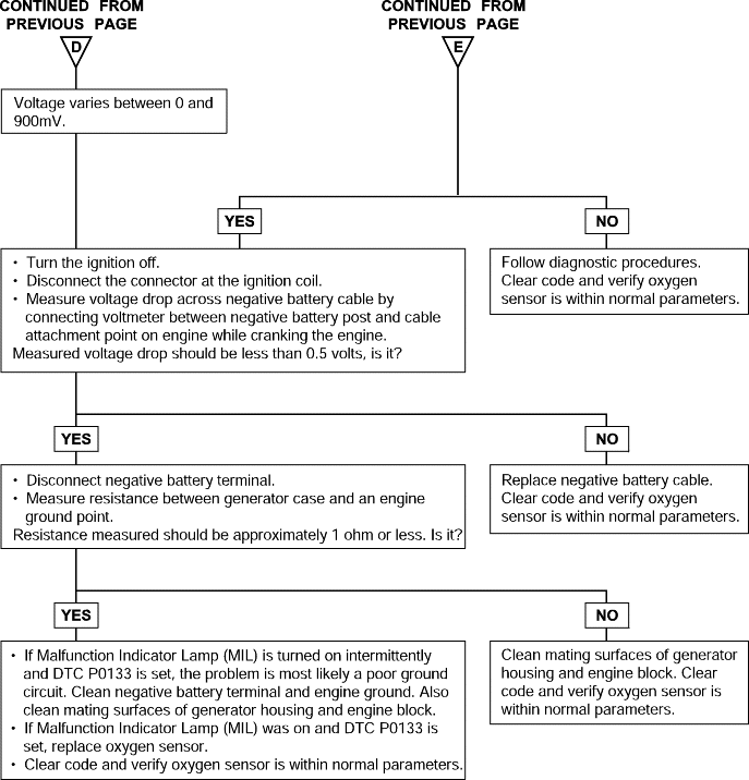
Background ● When the heated oxygen sensor begins to deteriorate, the oxygen sensor signal response becomes poor. ● The Powertrain Control Module forcibly varies the air/fuel mixture to make it leaner and richer and checks the response speed of the heated oxygensensor. In addition, the Powertrain Control Module also checks for an open circuit in the heated oxygen sensor output line. Malfunction; out-of-range ● Coolant temperature sensor: Normal. ● Heated oxygen sensor signal voltage has continued to be 0.1V or lower for 3 min. or more after the staring sequence was completed. ● Engine Coolant Temperature is higher than 80°C (176°F). ● Engine speed is higher than 1,200 r/min. ● Engine load is 25% or more. Judgment Criteria ● Input voltage supplied to the Powertrain Control Module interface circuit is 4.5V or more when 5V is applied to the heated oxygen sensor output linevia a resistor. Proper Operation ● Coolant temperature sensor: Normal. ● Engine Coolant Temperature is 50°C (122°F) or more. ● Engine speed is between 1,500 and 3,000 r/min or 1,100 and 3,000 r/min. ● Engine load is 25 - 60%. ● Intake air temperature is -10°C (14°F) or more. ● Under the closed loop air-fuel control. ● Monitoring Time: 8sec. Failure Criteria ● When the air-fuel ratio is forcibly changed (lean to rich and rich to lean), the heated oxygen sensor signal doesn't provide response within 1.28sec. ● Monitored only once per trip. | ● Heated oxygen sensor deteriorated ● Open circuit in heated oxygen sensor output line ● Powertrain control module failed |
DTC | Diagnostic item |
P0135 P0155 | Oxygen Sensor Heater Circuit Malfunction (Bank 1, Sensor 1) Oxygen Sensor Heater Circuit Malfunction (Bank 2, Sensor 1) |
To obtain a high purification rate for the CO, HC and NOx components of the exhaust gas, a three way catalytic converter is used, but for the most efficient use of the three-way catalytic converter, the ratio of the air must be precisely controlled so that it is always close to the stoichiometric air-fuel ratio. The oxygen sensor has the characteristic whereby its output voltage changes suddenly in the vicinity of the stoichiometric air-fuel ratio. This characteristic is used to detect the oxygen concentration in the exhaust gas and provide feedback to the computer for control of the air-fuel ratio. When the air-fuel ratio becomes LEAN, the oxygen concentration in the exhaust increases and the oxygen sensor informs the PCM of the LEAN condition. When the air-fuel ratio is RICHER than the stoichiometric air-fuel ratio the oxygen concentration in the exhaust gas is reduced and the oxygen sensor informs the PCM of theRICH condition.
The PCM determines by the electromotive force from the oxygen sensor whether the air-fuel ratio is RICH or LEAN and controls the injection time accordingly. However, if malfunction of the oxygen sensor causes output of abnormal electromotive force, the PCM is unable to perform an accurate air-fuel ratio control. The heated oxygen sensors include a heater which heats the sensing element. The heater is controlled by the PCM. When the intake air volume is low (the temperature of the exhaust gas is low), current flows to the heater to heat the sensor for accurate oxygen concentration detection.
DTC detection condition | Probable cause |
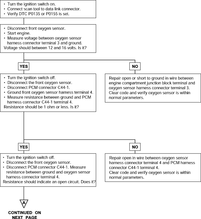
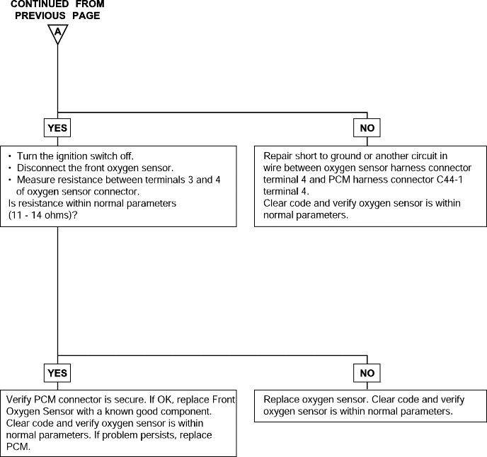
Background ● The Powertrain Control Module checks whether the heater current is within a specified range when the heater is energized. Check Area ● Battery voltage is between 12 and 16V. Judgment Criteria ● The heater current of the front heated oxygen sensor heater (Bank 1 Sensor 1 and Bank 2 Sensor 1) has continued to be 0.2 A or less, or 3.5 Aor higher for 6 sec. ● Monitored only once per trip. | ● Open or shorted oxygen sensor heater circuit ● Open circuit in oxygen sensor heater ● Powertrain control module failed |

DTC | Diagnostic item |
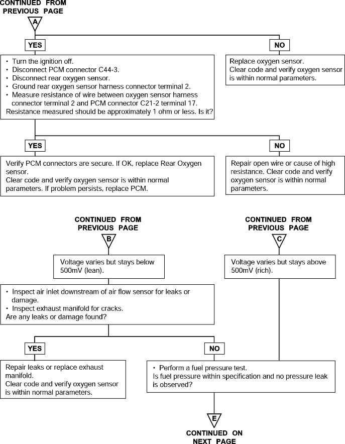
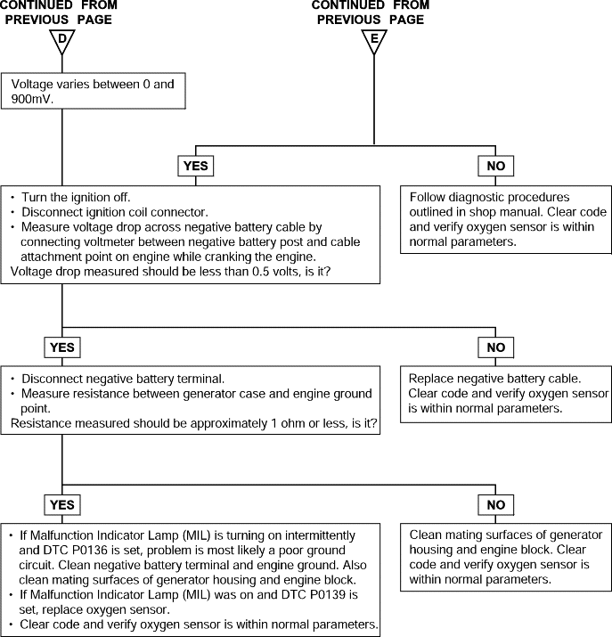
P0136 P0139 P0140 | Oxygen Sensor Circuit Malfunction - Open (Bank 1, Sensor 2) Oxygen Sensor Circuit Malfunction (Bank 1, Sensor 2) Oxygen Sensor Circuit Malfunction - Short (Bank 1, Sensor 2) |
To obtain a high purification rate for the CO, HC and NOx components of the exhaust gas, a three way catalytic converter is used, but for the most efficient use of the three-way catalytic converter, the ratio of the air must be precisely controlled so that it is always close to the stoichiometric air-fuel ratio. The oxygen sensor has the characteristic whereby its output voltage changes suddenly in the vicinity of the stoichiometric air-fuel ratio. This characteristic is used to detect the oxygen concentration in the exhaust gas and provide feedback to the computer for control of the air-fuel ratio. When the air-fuel ratio becomes LEAN, the oxygen concentration in the exhaust increases and the oxygen sensor informs the PCM of the LEAN condition. When the air-fuel ratio is RICHER than the stoichiometric air-fuel ratio the oxygen concentration in the exhaust gas is reduced and the oxygen sensor informs the PCM of theRICH condition.
The PCM determines by the electromotive force from the oxygen sensor whether the air-fuel ratio is RICH or LEAN and controls the injection time accordingly. However, if malfunction of the oxygen sensor causes output of abnormal electromotive force, the PCM is unable to perform an accurate air-fuel ratio control. The heated oxygen sensors include a heater which heats the sensing element. The heater is controlled by the PCM. When the intake air volume is low (the temperature of the exhaust gas is low), current flows to the heater to heat the sensor for accurate oxygen concentration detection.
DTC detection condition | Probable cause |
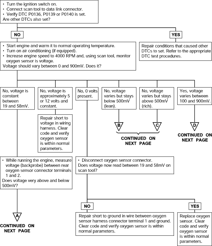
Background ● The Powertrain Control Module checks for an open circuit in the heated oxygen sensor output line. Normal values ● Coolant temperature sensor: Normal. ● Heated oxygen sensor signal voltage has continued to be 0.1V or lower for 3 min. or more after the staring sequence was completed. ● Engine coolant temperature is 80°C (176°F) or more. ● Engine speed is higher than 1,200 r/min. ● Engine load is 25% or more. ● Monitoring Time: 7 - 10 sec. Items to Check ● Input voltage supplied to the Powertrain Control Module interface circuit is 4.5V or more when 5V is applied to the heated oxygen sensor output linevia a resistor. ● Making the air-fuel ratio 15% richer doesn't result in raising the heated oxygen sensor output voltage beyond 0.1V. | ● Heated oxygen sensor failed ● Open circuit in heated oxygen sensor output line ● Powertrain control module failed |

DTC | Diagnostic item |
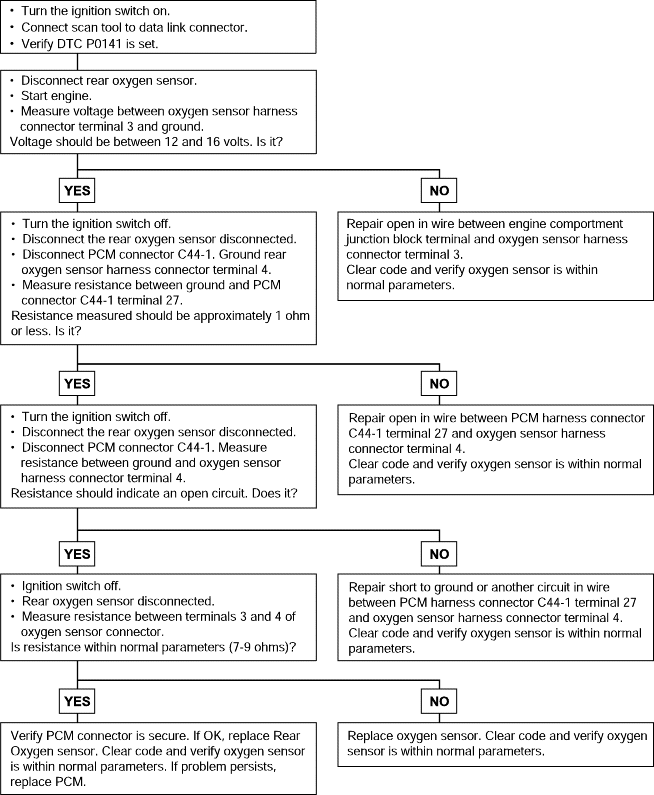
P0141 P0161 | Oxygen Sensor Heater Circuit Malfunction (Bank 1, Sensor 2) Oxygen Sensor Heater Circuit Malfunction (Bank 2, Sensor 2) |
To obtain a high purification rate for the CO, HC and NOx components of the exhaust gas, a three way catalytic converter is used, but for the most efficient use of the three-way catalytic converter, the ratio of the air must be precisely controlled so that it is always close to the stoichiometric air-fuel ratio. The oxygen sensor has the characteristic whereby its output voltage changes suddenly in the vicinity of the stoichiometric air-fuel ratio. This characteristic is used to detect the oxygen concentration in the exhaust gas and provide feedback to the computer for control of the air-fuel ratio. When the air-fuel ratio becomes LEAN, the oxygen concentration in the exhaust increases and the oxygen sensor informs the PCM of the LEAN condition. When the air-fuel ratio is RICHER than the stoichiometric air-fuel ratio the oxygen concentration in the exhaust gas is reduced and the oxygen sensor informs the PCM of theRICH condition.
The PCM determines by the electromotive force from the oxygen sensor whether the air-fuel ratio is RICH or LEAN and controls the injection time accordingly. However, if malfunction of the oxygen sensor causes output of abnormal electromotive force, the PCM is unable to perform an accurate air-fuel ratio control. The heated oxygen sensors include a heater which heats the sensing element. The heater is controlled by the PCM. When the intake air volume is low (the temperature of the exhaust gas is low), current flows to the heater to heat the sensor for accurate oxygen concentration detection.
DTC detection condition | Probable cause |
Background ● The Powertrain Control Module checks whether the heater current is within a specified range when the heater is energized. Check Area ● Battery voltage is between 12 and 16V. Judgment Criteria ● The heater current of the front heated oxygen sensor heater (Bank 1 Sensor 1 and Bank 2 Sensor 1) has continued to be 0.2 A or less, or 3.5 Aor higher for 6 sec. ● Monitored only once per trip. | ● Open or shorted oxygen sensor heater circuit ● Open circuit in oxygen sensor heater ● Powertrain control module failed |

DTC | Diagnostic item |
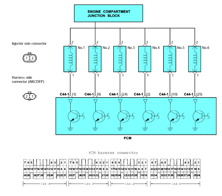
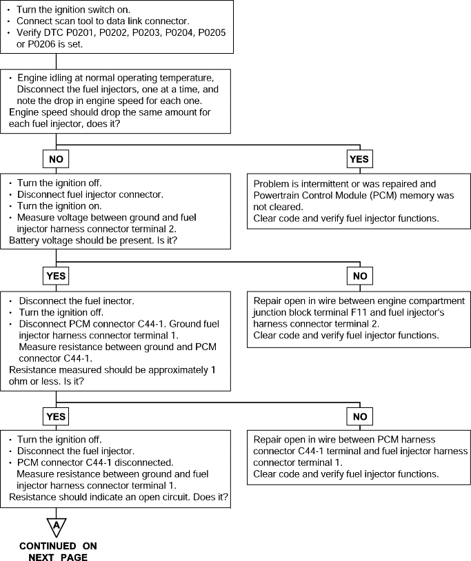
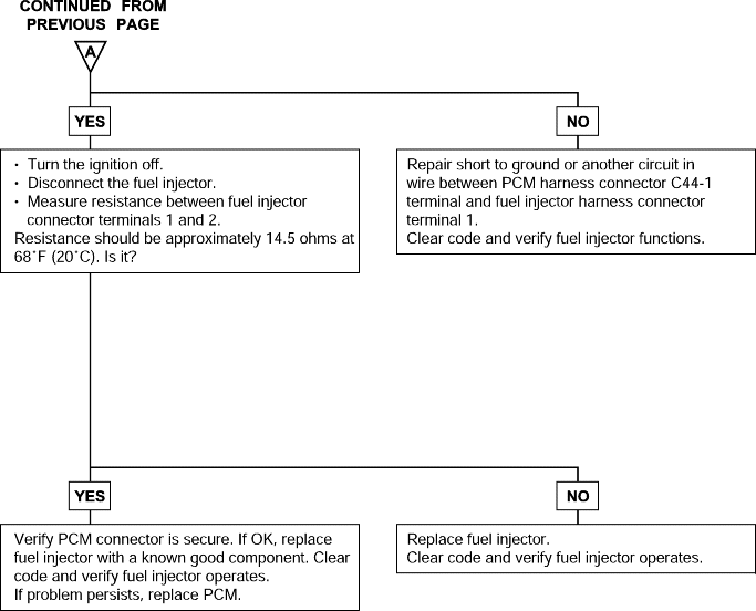
P0201, P0202 P0203, P0204 P0205, P0206 | Injector Circuit Malfunction (Cylinder-1, Cylinder-2, Cylinder-3, Cylinder-4, Cylinder-5, Cylinder-6) |
The fuel injectors are solenoid operated valves that are normally closed. When a fuel injector solenoid is energized (pulsed) the injector needle valve moves, allowing pressurized fuel to pass through the injector and mix with the air entering the engine. Each fuel injector (there is one for each engine cylinder) is mounted in the intake manifold and is positioned to spray fuelinto a cylinder head intake port.
The Powertrain Control Module (PCM) controls injector timing and pulse width (how long the fuel injectors are turned on). The PCM pulses the fuel injectors based on information provided by its network of engine sensors. The PCM uses the crankshaft position sensor to determine when to pulse the injectors. Engine coolant temperature, intake air temperature, air flow and throttle position data are all used by the PCM to calculate injector pulsewidth.
The PCM also uses its network of sensors to determine whether all injectors should be pulsed at the same time (simultaneous injection) or each injector should be pulsed individually (sequential injection). Sequential injection is almost always used during normal engine operation and simultaneous injectionmay be used when the engine is being cranked.
DTC detection condition | Probable cause |
Background ● A surge voltage is generated when the injectors are driven and the current flowing to the injector coil is shut off. ● The Powertrain Control Module checks this surge voltage. Normal Operation ● The engine speed is between 50 and 1,000 r/min ● Throttle position sensor output voltage is 1.16V or less. ● Monitoring Time: 4 sec. Malfunction ● Injector coil surge voltage (system voltage +2V) has not been detected for 4 sec. | ● Failed injector ● Open or shorted injector circuit, or loose connector ● Failed powertrain control module |
DTC | Diagnostic item |
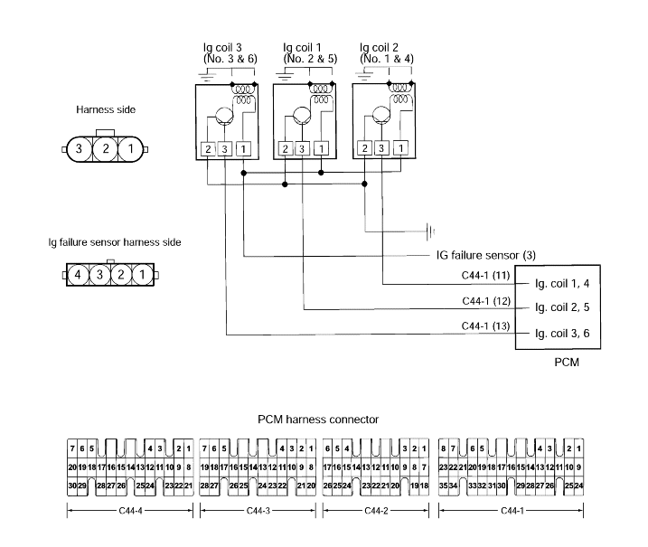
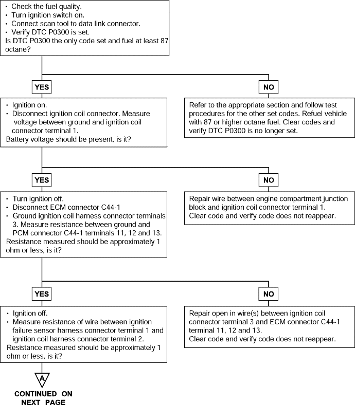
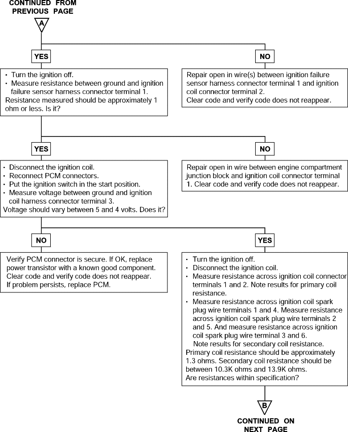
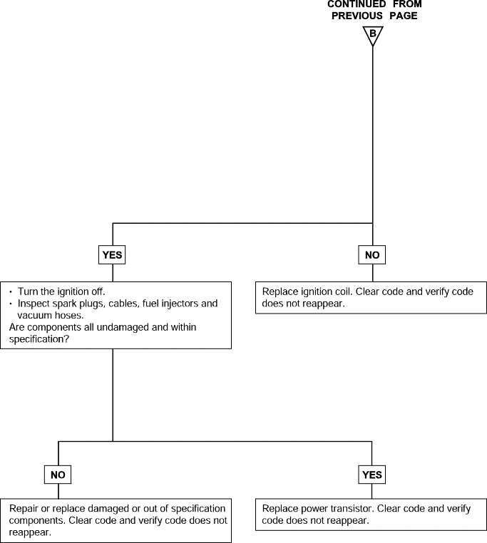
P0300 | Random Misfire Detected |
With the ignition switch ON or START, voltage is applied to the ignition coil. High tension leads go to each cylinder from the ignition coil. The ignition coil fires two spark plugs every power stroke (the cylinder under compression and the cylinder on the exhaust stroke). Coil number one fires cylinders 1 and 4. Coil number two fires cylinders 2 and 5. And coil number three firescylinders 3 and 6.
The ignition power transistor, controlled by the Powertrain Control Module (PCM), provides a switching circuit to ground for energizing the primary ignition coils. When a primary ignition coil is energized and deenergized, the secondary coil produces a high voltage spike across the attached spark plugs. At the same time, the tachometer interface (part of the ignition power transistor) provides the PCM and Transaxle Control Module (TCM) with an RPMsignal.
DTC detection condition | Probable cause |
Background ● If a misfire occurs while the engine is running, the engine speed suddenly changes. ● The Powertrain Control Module checks for changes in the engine speed by monitoring the CKP signal. Normal Operation ● Five seconds or more have passed after the engine has started. ● The engine speed is between 500 and 6,000 r/min. ● The engine Coolant Temperature is higher than -10°C(14°F). ● The intake air temperature is higher than -10°C (14°F). ● There is no sudden acceleration/deceleration such as during a shift change. Abnormal Operation (a change in the rate of angular acceleration by the crankshaft is monitored for misfire detection.) ● A misfire has occurred more frequently than allowed during the last 200 revolutions [when the catalyst temperature is higher than 950°C (1,742°F)]. ● A misfire has occurred more frequently than the allowed number of times (2%) during 1,000 motor revolutions. | ● Failed ignition system part(s) ● Poor crankshaft position sensor signal ● Incorrect air/fuel ratio ● Low compression ● Failed engine coolant temperature sensor ● Timing belt missing teeth ● Failed injector ● Failed powertrain control module |
DTC | Diagnostic item |
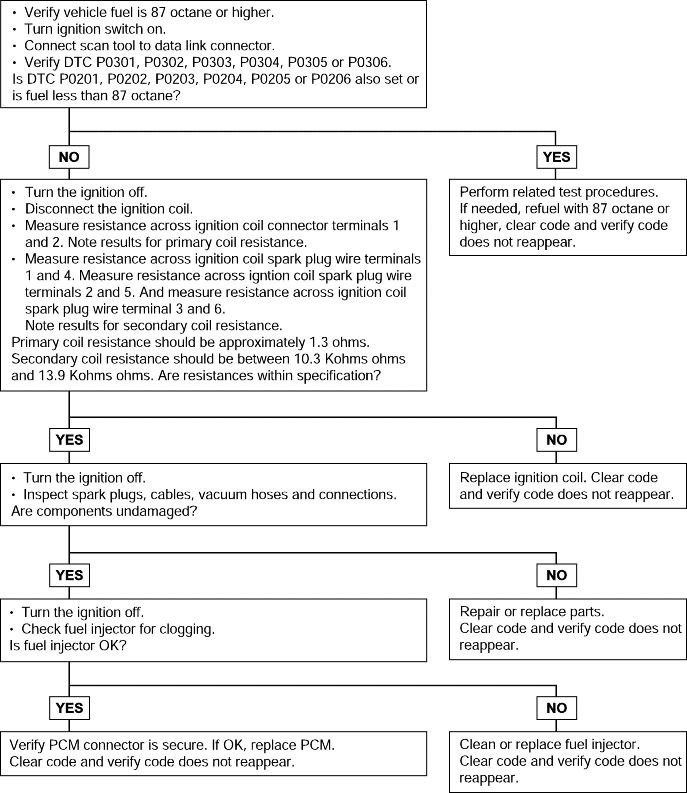
P0301, P0302, P0303, P0304, P0305, P0306 | Misfire detected (Cylinder-1, Cylinder-2, Cylinder-3, Cylinder-4, Cylinder-5, Cylinder-6) |
With the ignition switch ON or START, voltage is applied to the ignition coil. High tension leads go to each cylinder from the ignition coil. The ignition coil fires two spark plugs every power stroke (the cylinder under compression and the cylinder on the exhaust stroke). Coil number one fires cylinders 1 and 4. Coil number two fires cylinders 2 and 5. And coil number three firescylinders 3 and 6.
The ignition power transistor, controlled by the Powertrain Control Module (PCM), provides a switching circuit to ground for energizing the primary ignition coils. When a primary ignition coil is energized and deenergized, the secondary coil produces a high voltage spike across the attached spark plugs. At the same time, the tachometer interface (part of the ignition power transistor) provides the PCM and Transaxle Control Module (TCM) with an RPMsignal.
DTC detection condition | Probable cause |
Background ● If a misfire occurs while the engine is running, the engine speed suddenly changes. ● The Powertrain Control Module checks for changes in the engine speed. Normal Operation ● Five seconds or more have passed after the engine was started. ● The engine speed is between 500 and 6,000 rpm. ● The engine Coolant Temperature is higher than -10°C (14°F). ● The intake air temperature is higher than -10°C (14°F). ● The engine is not making sudden acceleration/deceleration such as during a shift. Malfunction Criteria (a change in the angular acceleration of the crankshaft is used for misfire detection.) ● A misfire has occurred more frequently than allowed for during the last 200 revolutions [when the catalyst temperature is higher than 950°C (1,742°F)]. ● A misfire has occurred more frequently than the allowed number of times (2%) during 1,000 motor revolutions. | ● Failed ignition system related part(s) ● Poor crankshaft position sensor signal ● Incorrect air/fuel ratio ● Low compression ● Failed engine coolant temperature sensor ● Timing belt missing teeth ● Failed injector ● Failed EGR valve ● Failed powertrain control module |

DTC | Diagnostic item |
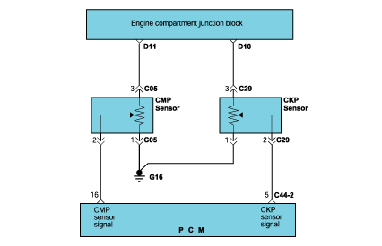
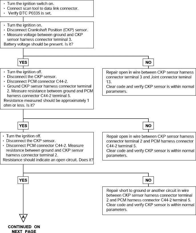
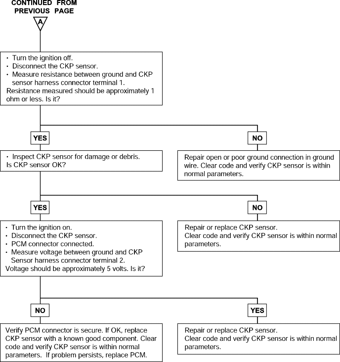
P0335 | Crankshaft Position Sensor Circuit Malfunction |
The Hall-effect Crankshaft Position (CKP) sensor consists of a magnet and coil located next to the flywheel. The voltage signal from the CKP sensor allows the Powertrain Control Module (PCM) to determine the engine of theRPM and Crankshaft Position.
DTC detection condition | Probable cause |
Background ● When the engine is running, the Crankshaft Position sensor outputs a pulse signal. ● The Powertrain Control Module checks whether the pulse signal is input while the engine is cranking. Normal Operating condition ● Engine is being cranked. Normal Operation ● Sensor output voltage has not changed (no pulse signal is input) for 4 sec. Malfunction ● Normal signal pattern has not been input for cylinder identification from the crankshaft position sensor signal and camshaft position sensor signalfor 4 sec. | ● Failed crankshaft position sensor ● Open or shorted crankshaft position sensor circuit ● Failed powertrain control module |
DTC | Diagnostic item |
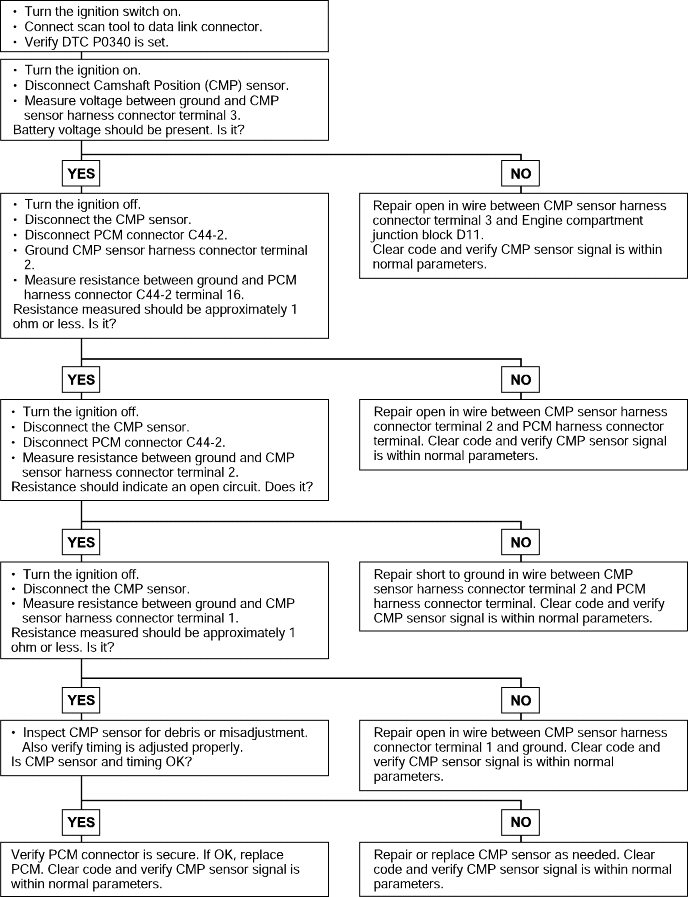
P0340 | Camshaft Position Sensor Circuit Malfunction |
The Camshaft Position (CMP) sensor senses the Top Dead Center (TDC) point of the #1 cylinder in the compression stroke. The CMP sensor signalallows the PCM to determine when to operate the fuel injectors.
DTC detection condition | Probable cause |
Normal Operation ● When the engine is running, the Camshaft Position sensor outputs a pulse signal. ● The Powertrain Control Module checks whether the pulse signal is input. Malfunction ● Normal signal pattern has not been input for cylinder identification from the camshaft position sensor signal for 4 sec. | ● Camshaft Position sensor malfunction ● Open or shorted camshaft position sensor circuit or loose connector ● Powertrain control module failed |

DTC | Diagnostic item |
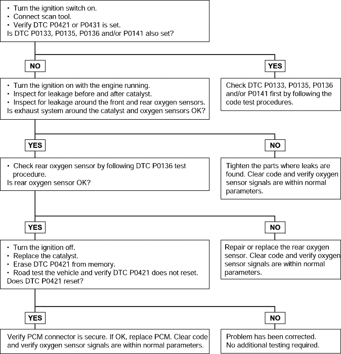
P0421 P0431 | Warm Up Catalyst Efficiency Below Threshold (Bank 1) Warm Up Catalyst Efficiency Below Threshold (Bank 2) |
The PCM compares the waveform of the front oxygen sensor with the waveform of the rear oxygen sensor to determine whether or not catalyst performance has deteriorated. Air-fuel ratio feedback compensation keeps the waveform of the front oxygen sensor repeatedly changing back and forth from rich tolean.
If the catalyst is functioning normally, the waveform of the rear oxygen sensor switches back and forth between rich and lean much more slowly than the waveform of the front oxygen sensor. When both waveforms change at a similarrate, catalyst performance has deteriorated.
DTC detection condition | Probable cause |
Normal Operation ● The signal from the rear Oxygen sensor differs from the front Oxygen sensor. This is because the catalytic converter purifies, the exhaust gas. When the catalytic converter has deteriorated, the signal from the rear becomessimilar to that of the front. ● The Powertrain Control Module checks the outputs of both oxygen sensor signals. Normal Operation ● Engine speed is 3,000 rpm or higher. ● Closed throttle position switch: OFF ● Closed loop operation ● Monitoring Time: 140 sec. Malfunction ● The front and rear Oxygen sensor signals are similar. | ● Catalytic converter deteriorated ● Heated oxygen sensor failed ● Powertrain control module failed |
DTC | Diagnostic item |
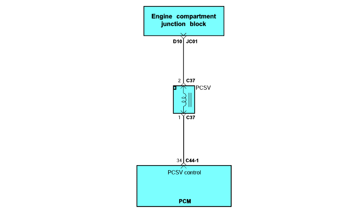
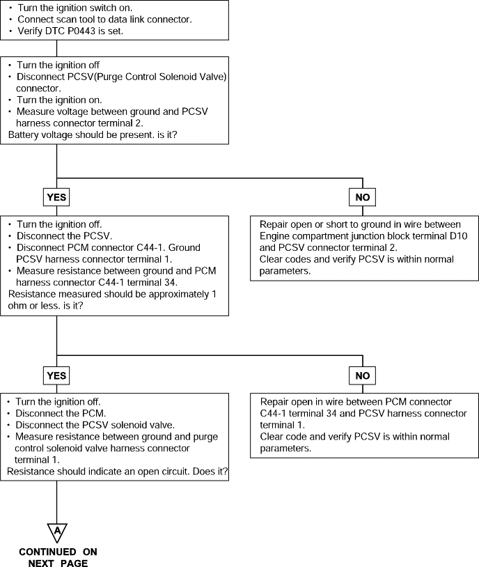
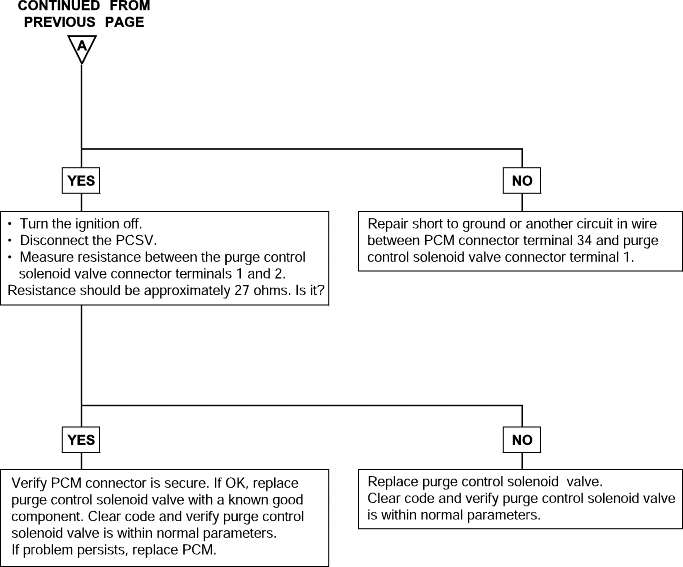
P0443 | Purge Control Solenoid Valve Malfunction |
The evaporative system reduces hydrocarbon emission by trapping fuel tank vapors until they can be burned as part of the incoming fuel charge. Evaporating fuel is stored in a charcoal canister until it can be flushedinto the intake manifold.
DTC detection condition | Probable cause |
Normal Operation ● The Powertrain Control Module checks current flows in the evaporative emission purge solenoid drive circuit when the solenoid is ON and OFF. Normal Operation ● Battery voltage is 10V or higher. Malfunction ● The solenoid coil surge voltage (system voltage +2V) is not detected when the EVAP emission vent solenoid is turned on/off. | ● Evaporative emission purge control solenoid valve failed ● Open or shorted evaporative emission purge solenoid circuit, or loose connector ● Powertrain control module failed |
DTC | Diagnostic item |
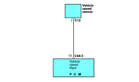
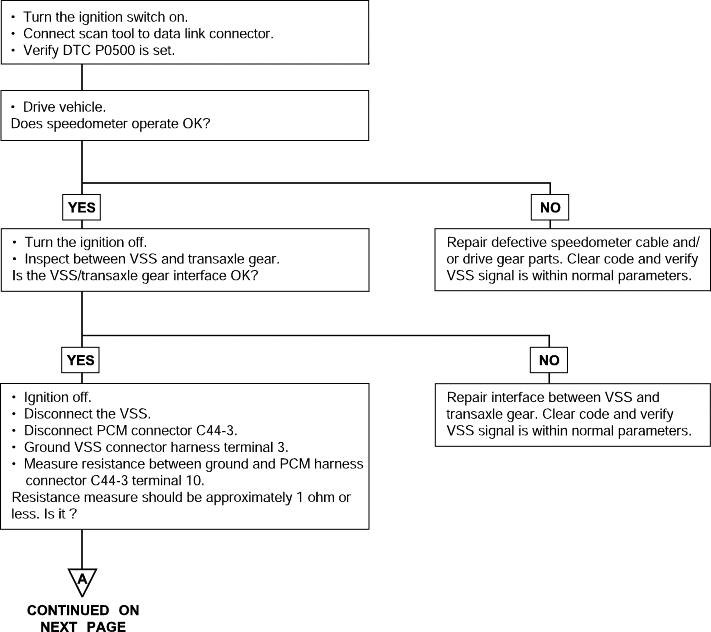
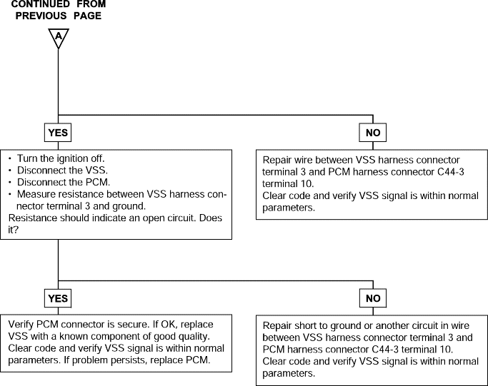
P0500 | Vehicle Speed Sensor Malfunction |
The vehicle speed sensor outputs a pulse signal while the vehicle is driven.
The powertrain control module checks whether the pulse signal is present.
DTC detection condition | Probable cause |
Normal Operation ● The vehicle speed sensor outputs a pulse signal while the vehicle is driven. ● The Powertrain Control Module checks whether the pulse signal is present. Normal Operation ● Closed throttle position switch: OFF ● Engine speed is 3,000 rpm or more. ● Engine load is 70% or more. Malfunction ● Sensor output voltage has not changed (no pulse signal is input) for 4 sec. | ● Failed vehicle speed sensor ● Open or shorted vehicle-speed sensor circuit, or loose connector ● Failed powertrain control module |
DTC | Diagnostic item |
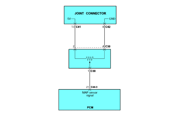
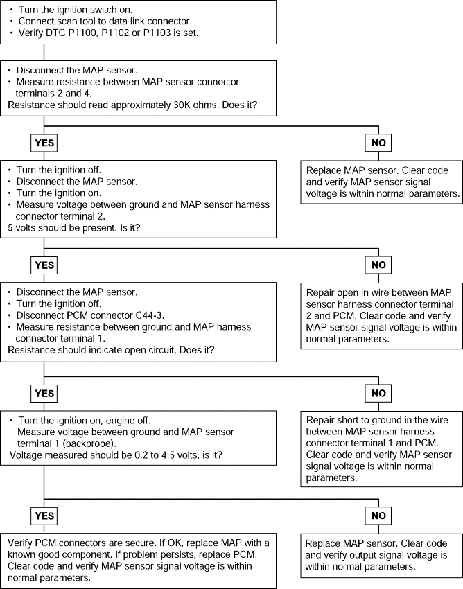
P1100 P1102 P1103 | Manifold Absolute Pressure Sensor Circuit Malfunction Manifold Absolute Pressure Sensor Circuit Malfunction (Low Voltage) Manifold Absolute Pressure Sensor Circuit Malfunction (High Voltage) |
The MAP sensor is essentially a strain gauge used to measure the pressure in the surge tank. Inside the sensor is a metal diaphragm with a small wire attached. The diaphragm flexes according to changes in pressure. When the diaphragm flexes, the wire attached to it stretches, changing the resistance of the wire. The Powertrain Control Module (PCM) applies five volts to the MAP sensor and measures the voltage drop across the sensor. The sensor output is in volts and as pressure decreases, the voltage drop across the sensorincreases.
DTC detection condition | Probable cause |
Normal Operation ● The MAP sensor outputs a voltage which corresponds to the pressure of the surge tank. ● The Powertrain Control Module checks whether this voltage is within a specified range. Normal Operation ● Ignition switch : ON ● Sixty seconds or more have passed since the staring sequence was completed. ● Battery voltage is 8V or more. Malfunction ● The sensor output voltage has continued to be 4.5V or higher [corresponding to a surge tank pressure of 114 kPa(17psi) or higher] for 4 sec. ● The sensor output voltage has continued to be 1.95V or lower [corresponding to a surge tank pressure of 50 kPa(7.4 psi) or lower] for 4 sec. | ● Failed MAP sensor ● Open or shorted MAP sensor circuit, or loose connector ● Failed powertrain control module |
DTC | Diagnostic item |
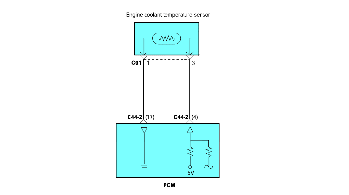
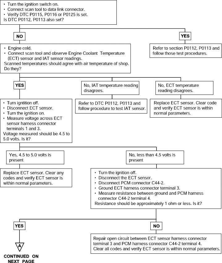
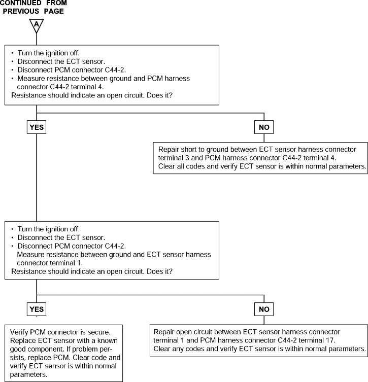
P0115 P0116 P0125 | Engine Coolant Temperature Circuit Malfunction (Open/Short) Engine Coolant Temperature Circuit Drift Insufficient Coolant Temperature For Feed-Back Control |
The Engine Coolant Temperature (ECT) sensor is located in a coolant passage of the cylinder head. The ECT sensor is a variable resistor whose resistance changes as the temperature of the engine coolant flowing past the sensor changes. When the coolant temperature is low, the sensor resistance is high; when the coolant temperature is high, the sensor resistance is low. The Powertrain Control Module (PCM) checks ECT voltage fifty times per second and uses the information to help adjust the fuel injector pulse width and ignition timing. When the temperature sensed is very cold, the PCM enrichesthe fuel mixture.
DTC detection condition | Probable cause |
Background ● The engine coolant temperature sensor converts the engine coolant temperature to a voltage and outputs it. ● The Powertrain Control Module checks whether the voltage is within a specified range. In addition, it checks that the engine coolant temperature(signal) does not drop while the engine is warming up. Malfunction; out-of-range ● Sensor output voltage has continued to be 4.6V or higher [corresponding to a coolant temperature of -45°C (-49°F) or lower] for 4 sec. ● Sensor output voltage has continued to be 0.1V or lower [corresponding to a coolant temperature of 140°C (284°F) or higher] for 4 sec. Malfunction; out-of-range ● Sensor output voltage increased from a value lower than 1.6V to a value higher than 1.6V [Coolant temperature decreases from higher than 40°C (104°F) temperature to lower than 40°C (104°F) temperature.]. ● Sensor output voltage has continued to be 1.6V or higher for 5 min. Judgment Criteria, Proper Performance ● The Engine Coolant Temperature is approx. 40°C (104°F) or less after starting sequence is completed. ● Approx. 60 - 300 seconds have passed for the engine coolant temperature to rise to about 40°C (104°F) after starting sequence was completed. | ● Engine Coolant Temperature sensor failed. ● Open or shorted Engine Coolant Temperature sensor circuit, or loose connector. ● Powertrain Control Module failed. |
