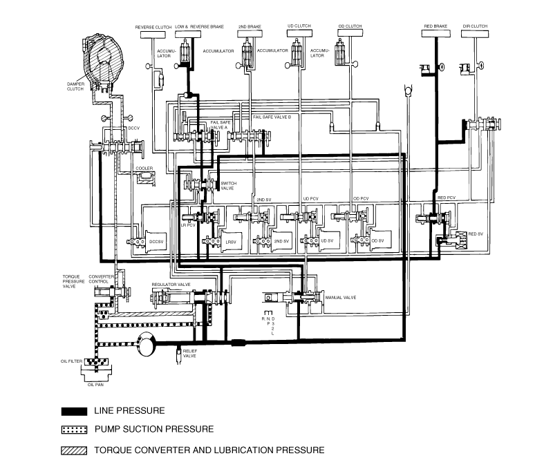
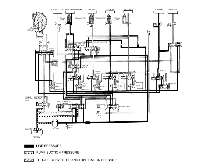
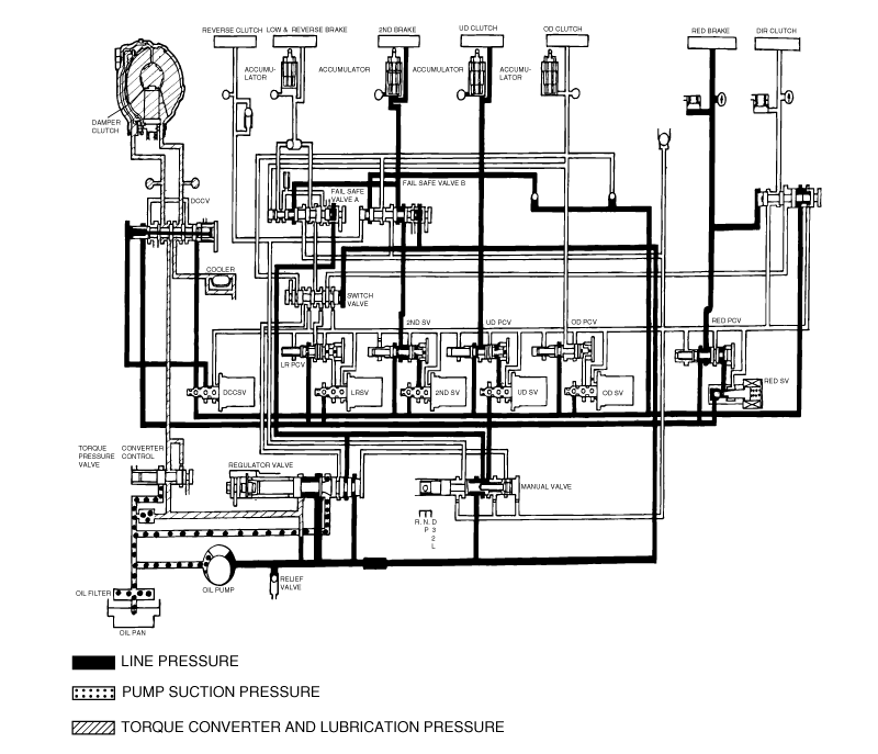
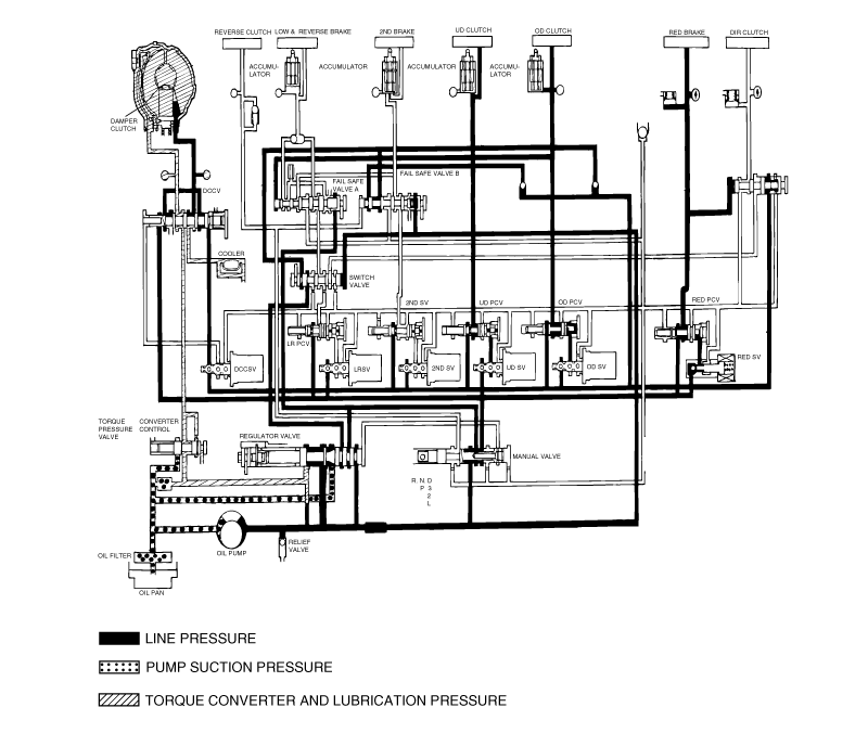
Tighten the transaxle range switch body mounting bolts to the specified torque. Make sure at this time that the position of the switch body did notmove.
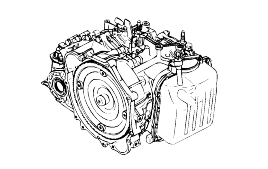
Drive the vehicle until the fluid temperature rises to the normal temperature (70-80°C).
Park the vehicle on a level surface.
Move the selector lever through all positions to fill the torque converter and the hydraulic circuits with fluid, and then move the selectorlever to the N position.
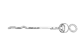
After wiping off any dirt around the oil level gauge(dipstick), remove the oil level gauge and check the condition of the fluid.
If the fluid smells burned, it means that the fluid has been contaminated by fine particles from the bushings and frictionmaterials, a transaxle overhaul may be necessary.
Check that the fluid level is at the HOT mark on the oil level gauge. If the fluid level is lower than this, pour in more fluid until the level reaches the HOT mark. Automatic transmission fluid : GENUINE DIAMOND ATFSP-III.
If the fluid level is low, the oil pump will draw in air along with the fluid, which will cause bubbles to form inside the hydraulic circuit. This will in turn cause the hydraulic pressure to drop, which will result in late shifting and slipping of the clutches and brakes. If there is too much fluid, the gears can churn it up into foam and cause the same conditions that can occur with low fluid level. In either case, air bubbles can cause overheating and oxidation of the fluid which can interfere with normal valve, clutch, and brake operation. Foaming can also result in fluid escaping from the transmission vent, in which case it may be mistakenfor a leak.
Securely insert the oil level gauge.
The fluid and the oil filters should always be replaced when overhauling the transmission or after the vehicle has been driven under severe conditions. The replacement procedures are given below. Furthermore, the oil filters are special filters which are only to be used for the automatic transmission.
Disconnect the hose which connects the transmission and the oil cooler (inside the radiator).
Start the engine and let the fluid drain out.
Running conditions : N range with engine idling. |
The engine should be stopped within one minute after it is started. If the fluid has all drained out before then, the engineshould be stopped at that point.
Remove the drain plug from the bottom of the transmission case to drain the fluid.
Install the drain plug via the gasket, and tighten it the specified torque.
Tightening torque : 32 Nm |
Pour the new fluid in through the oil filler tube.
Stop pouring if the full volume of fluid cannot be poured in.
Repeat the procedure in step (2).
Check the old fluid for contamination. If it has been contaminated, repeat the steps (5) and (6).
Pour the new fluid in through the oil filler tube.
Reconnect the hose which was disconnected in step (1) above, and firmly replace the oil level gauge.
(In case of this "replace", this means after wiping off any dirt around the oil level gauge, insert it into the filler tube.)
Start the engine and run it at idle for 1-2 minutes.
Move the select lever through all positions, and then move it to the N position.
Drive the vehicle until the fluid temperature rises to the normal temperature (70-80°C), and then check the fluid level again. The fluidlevel must be at the HOT Mark.
Firmly insert the oil level gauge into the oil filler tube.
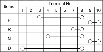
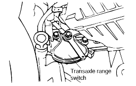
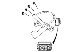
Set the selector lever to the "N" position.
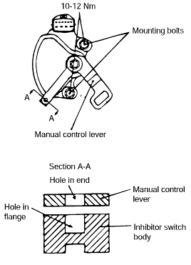
Loosen the control cable to manual control lever coupling nut to free the cable and lever.
Set the manual control lever to the neutral position.
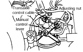
Loosen the transaxle range switch body mounting bolts and then turn the transaxle range switch body so the hole in the end of the manual control lever and the hole (cross section A-A in the figure) in the flange of thetransaxle range switch body flange are aligned.
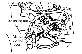
Tighten the transaxle range switch body mounting bolts to the specified torque. Make sure at this time that the position of the switch body did notmove.

Gently pull the transmission control cable in the direction of the arrow, and then tighten the adjusting nut.
Check that the selector lever is in the "N" position.
Check that each range on the transmission side operates and functions correctly for each position of the selector lever.
THROTTLE POSITION SENSOR CHECK.
The TP Sensor is a variable resistor type that rotates with the throttle body shaft to sense the throttle valve angle. As the throttle shaft rotates, the output voltage of the TP Sensor changes. The ECM detects the throttlevalve opening based on voltage change. (Refer to FL-section).
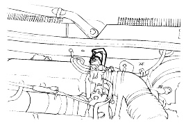
OIL TEMPERATURE SENSOR CHECK
Remove the oil temperature sensor.
Measure the resistance between terminals No.1 and No.2 of the oil temperature sensor connector.
Oil temperature (°C) | Resistance (KΩ) |
0 | 16.7-20.5 |
100 | 0.57-0.69 |
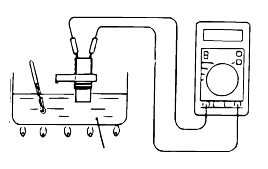
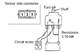
VEHICLE SPEED SENSOR CHECK
Remove the vehicle speed sensor and connect a 3-10 KΩ resistance as shown in the illustration.
Turn the shaft of the vehicle speed sensor and check that there is voltage between terminals 1-2 (1 turn = 4 pulses).
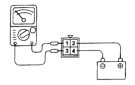
A/T CONTROL RELAY CHECK
Remove the A/T control relay.
Use jumper wires to connect A/T control relay terminal (2) to the battery (+) terminal and terminal (4) to the battery (-) terminal.
Check the continuity between terminal (1) and terminal (3) of the A/T control relay when the jumper wires are connected to and disconnectedfrom the battery.
If there is a problem, replace the A/T control relay.
Jumper wire | Continuity between terminal No.1 |
Connected | Continuity |
Disconnected | No continuity |
SOLENOID VALVE CHECK
Remove the valve body cover.
Disconnect the connectors of each solenoid valve.
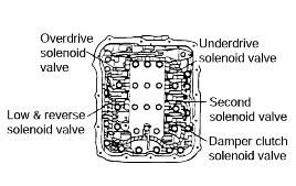
Measure the resistance between terminals 1 and 2 of each solenoid valve.
Name | Resistance |
Damper clutch solenoid valve | 2.7-3.4 Ω (at 20°C) |
Low and reverse solenoid valve | |
Second solenoid valve | |
Underdrive solenoid valve | |
Overdrive solenoid valve |
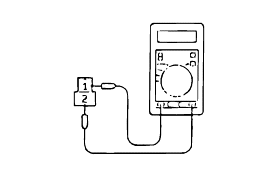
If the resistance is outside the standard value, replace the solenoid valve.
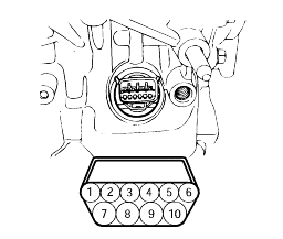
Resistance of the solenoid valve connector.
Terminal No. | Name | Resistance |
7 & 10 | Damper clutch solenoid valve | 2.7-3.4Ω (at 20°C) |
10 & 6 | Low and reverse solenoid valve | |
9 &4 | Second solenoid valve | |
9 & 3 | Underdrive solenoid valve | |
9 & 5 | Overdrive solenoid valve |
Do not let anybody stand in front of or behind the vehicle while this test is being carried out.
Check the automatic transmission fluid level and temperature and the engine coolant temperature.
● Fluid level : At the HOT mark on the oil level gauge ● Fluid temperature : 80-100°C ● Engine coolant temperature : 80-100°C |
Check 4 wheels.
Pull the parking brake lever on, with the brake pedal fully depressed.
Start the engine.
Move the selector lever to the D position, fully depress the accelerator pedal and take a reading of the maximum engine speed at this time.
The throttle should not be left fully open for any more than eight seconds.
If carrying out the stall test two or more times, move the selector lever to the N position and run the engine at 1,000 r/min to let the automatictransaxle fluid cool down before carrying out subsequent tests.
Standard value Stall speed : 2,000 - 2,900 r/min |
Move the selector lever to the R position and carry out the same test again.
Standard value Stall speed : 2,000 - 2,900 r/min |
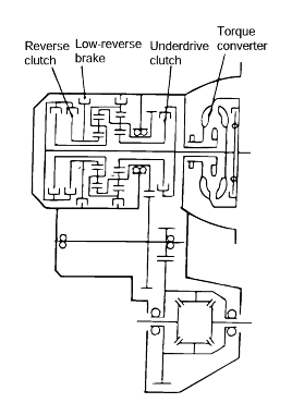
Stall speed is too high in both D and R ranges
Low line pressure
Low & reverse brake slippage
Stall speed is too high in D range only
Underdrive clutch slippage
Stall speed is too high in R range only
Reverse clutch slippage
Stall speed too low in both D and R ranges
Malfunction of torque converter
Insufficient engine output
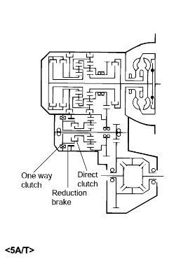
Warm up the engine until the automatic transaxle fluid temperature is 80-100°C.
Jack up the vehicle so that the wheels are free to turn.
Connect the special tools oil pressure gauge to each pressure discharge port.
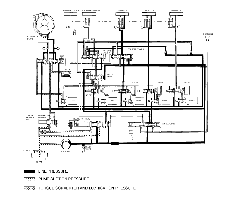
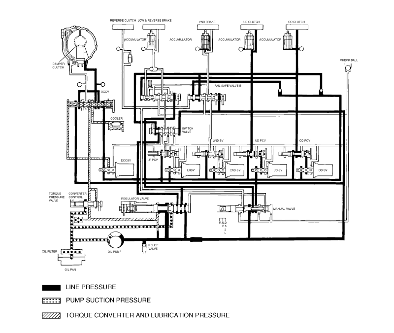
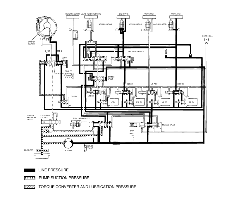
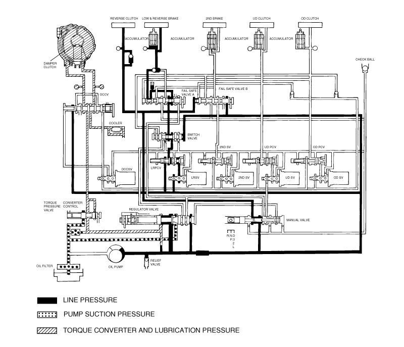
Measure the hydraulic pressure at each port under the conditions given in the standard hydraulic pressure table, and check that the measuredvalues are within the standard value ranges.
If a value is outside the standard range, correct the problem while referring to the hydraulic pressure test diagnosis table.
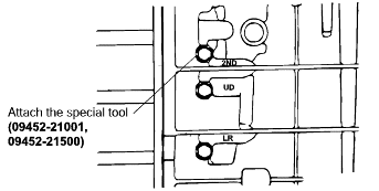
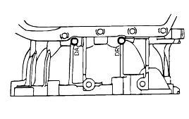
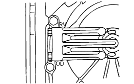
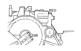
Measurement condition | Standard hydraulic pressure kPa (psi) | |||||||
Selector lever position | Shift position | Engine speed (rpm) | Under drive clutch pressure | Reverse clutch pressure | Overdrive clutch pressure | Low and reverse brake pressure | Second brake pressure | Torque converter pressure |
P | - | 2,500 | - | - | - | 310-390 (45-56) | - | 250-350 (36-56) |
R | Reverse | 2,500 | - | 1,270-1,770 (185-256) | - | 1,270-1,770 (185-256) | - | 500-700 (73-101) |
N | 2,500 | - | - | - | - | 310-390 (45-56) | - | 250-390 (36-56) |
D | 1st gear | 2,500 | 1,010-1,050 (146-152) | - | - | * 1,010-1,050 (146-152) | - | 500-700 (73-101) |
2nd gear | 2,500 | 1,010-1,050 (146-152) | - | - | - | 1,010-1,050 (146-152) | 500-700 (73-101) | |
3rd gear | 2,500 | 590-690 (85-100) | - | 590-690 (85-100) | - | - | 450-650 (65-94) | |
4th gear | 2,500 | - | - | 590-690 (85-100) | - | 590-690 (85-100) | 450-650 (65-94) | |
* L&R brake applied 0-3 mph only in D1
Measurement condition | Standard hydraulic pressure kPa/(psi) | |||||||||
Selector lever position | Shift position | Engine speed (rpm) | Under drive clutch pressure(UD) | Reverse clutch pressure (REV) | Overdrive clutch pressure(OD) | Low and reverse brake pressure(LR) | Second brake pressure (2ND) | Direct clutch pressure | Damper clutch release pressure(DR) | Reduction brake pressure |
P | - | 2,500 | - | - | - | 260-340 (38-49) | - | - | 220-360 (31-52) | 260-340 (38-49) |
R | Reverse | 2,500 | - | 1,270-1,770 (185-256) | - | 1,270-1,770 (185-256) | - | - | 500-700 (73-101) | 1270-1770 (185-256) |
N | Neutral | - | - | - | - | 260-340 (38-49) | - | - | 220-360 (31-52) | 260-340 (38-49) |
D | 1st gear | 2,500 | 1,010-1,050 (147-152) | - | - | 1,010-1,050 (147-152) | - | - | 500-700 (73-101) | 1010-1050 (147-152) |
2nd gear | 2,500 | 1,010-1,050 (147-152) | - | - | - | 1,010-1,050 (147-152) | - | 500-700 (73-101) | 1010-1050 (147-152) | |
3rd gear | 2,500 | 780-880 (113-128) | - | 780-880 (113-128) | - | - | - | 450-650 (65-94) | 780-880 (113-128) | |
4th gear | 2,500 | 780-880 (113-128) | - | 780-880 (113-128) | - | - | 780-880 (113-128) | 450-650 (65-94) | - | |
5th gear | 2,500 | - | - | 780-880 (113-128) | - | 780-880 (113-128) | 780-880 (113-128) | 450-650 (65-94) | - | |
Trouble symptom | Probable cause |
All hydraulic pressures are high | Incorrect transmission control cable adjustment |
Malfunction of the regulator valve | |
All hydraulic pressures are low | Incorrect transmission control cable adjustment |
Malfunction of the oil pump | |
Clogged internal oil filter | |
Clogged external oil filter | |
Clogged oil cooler | |
Malfunction of the regulator valve | |
Malfunction of the relief valve | |
Incorrect valve body installation | |
Hydraulic pressure is abnormal in "R" range only | Malfunction of the regulator valve |
Clogged orifice | |
Incorrect valve body installation | |
Hydraulic pressure is abnormal in "3" or "4" range only | Malfunction of the regulator valve |
Clogged orifice | |
Incorrect valve body installation | |
Malfunction of the overdrive solenoid valve | |
Malfunction of the overdrive pressure control valve | |
Malfunction of the regulator valve | |
Malfunction of the switch valve | |
Clogged orifice | |
Incorrect valve body installation | |
Only underdrive hydraulic pressure is abnormal | Malfunction of the oil seal K |
Malfunction of the oil seal L | |
Malfunction of the oil seal M | |
Malfunction of the underdrive solenoid valve | |
Malfunction of the underdrive pressure control valve | |
Malfunction of check ball | |
Clogged orifice | |
Incorrect valve body installation | |
Only reverse clutch hydraulic pressure is abnormal | Malfunction of the oil seal A |
Malfunction of the oil seal B | |
Malfunction of the oil seal C | |
Clogged orifice | |
Incorrect valve body installation | |
Only overdrive hydraulic pressure is abnormal | Malfunction of the oil seal D |
Malfunction of the oil seal E | |
Malfunction of the oil seal F | |
Malfunction of the overdrive solenoid valve | |
Malfunction of the overdrive pressure control valve | |
Malfunction check ball | |
Clogged orifice | |
Incorrect valve body installation | |
Only low and reverse hydraulic pressure is abnormal | Malfunction of the oil seal I |
Malfunction of the oil seal J | |
Malfunction of the low and reverse solenoid valve | |
Malfunction of the low and reverse pressure control valve | |
Malfunction of the switch valve | |
Malfunction of the fail safe valve A | |
Malfunction of check ball | |
Clogged orifice | |
Incorrect valve body installation | |
Only second hydraulic pressure is abnormal | Malfunction of the oil seal G |
Malfunction of the oil seal H | |
Malfunction of the oil seal O | |
Malfunction of the second solenoid valve | |
Malfunction of the second pressure control valve | |
Malfunction of the fail safe valve B | |
Clogged orifice | |
Incorrect valve body installation | |
Only reverse clutch hydraulic pressure is abnormal | Malfunction of the oil cooler |
Malfunction of the oil seal N | |
Malfunction of the damper clutch control solenoid valve | |
Malfunction of the damper clutch control valve | |
Malfunction of the torque converter pressure control valve | |
Clogged orifice | |
Pressure applied to non operating element | Incorrect valve body installation |
Incorrect transmission control cable adjustment | |
Malfunction of the manual valve | |
Malfunction of check ball | |
Incorrect valve body installation |
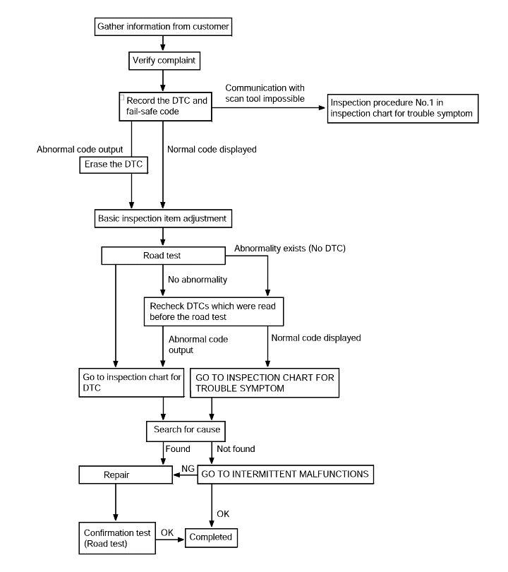
Connect the Hi Scan Pro to the data link connector for diagnosis.
Read the output diagnostic trouble codes. Then follow the remedy procedures according to the "DIAGNOSTIC TROUBLE CODE DESCRIPTION" on the following pages.
A maximum of 8 diagnostic trouble codes (in the sequence of occurrence) can be stored in the Random Access Memory (RAM) incorporated within the controlmodule.
The same diagnostic trouble code can be stored one time only.
If the number of stored diagnostic trouble codes or diagnostic trouble patterns exceeds 8, already stored diagnostic trouble codes will be erasedin sequence, beginning with the oldest.
Do not disconnect the battery until all diagnostic trouble codes or diagnostic trouble patterns have been read out, because all stored diagnostic trouble codes or diagnostic trouble patterns will be cancelled when the batteryis disconnected.
If the fail-safe system is activated and the transaxle is locked in third gear, the diagnostic trouble code in the fail-safe code description will be stored in the RAM. Three of these diagnostic trouble codes can bestored.
The cancellation will occur if, with the transaxle locked in third gear, the ignition key is turned to the OFF position, but the diagnostic troublecode is stored in the RAM.
Memorization.
Up to 8 diagnosis items and 3 fail-safe items can be memorized.
If the memory capacity is exceeded, diagnosis and fail-safe items in the memory are overwritten, starting with the oldest.
No code can be memorized more than once.
Diagnosis Code Deletion.
Automatic Deletion
All diagnosis codes are deleted from memory the 200th time the ATF temperature reaches 50°C after memorization of the most recent diagnosis code.
Forced Deletion.
The ignition switch is ON.
There is no detection pulse from the crank angle sensor.
There is no detection pulse from the output shaft speed sensor.
There is no detection pulse from the vehicle speed sensor.
The fail-safe function is not operational.
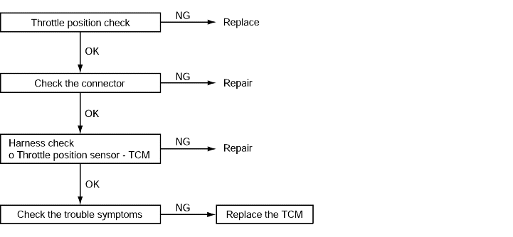
Code No. P1704, P1703, P1702 throttle position sensor system | Probable cause |
If the TPS output voltage is 4.8 V or higher when the engine is idling, the output is judged to be too high and diagnostic trouble code No.P1704 is set. If the TPS output voltage is 0.2 V or lower at times other than when the engine is idling, the output is judged to be too low and diagnostic trouble code No.P1703 is set. If the TPS output voltage is 0.2 V or lower or if it is 1.2 V or higher when the engine is idling, the TPS adjustment is judged to be incorrect and diagnostic trouble code No.P1702is set. | ● Malfunction of the throttle position sensor ● Malfunction of connector ● Malfunction of the TCM |
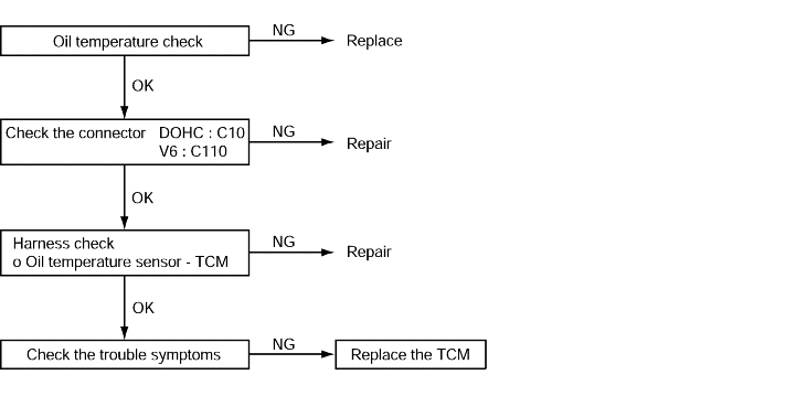
Code No. P0712, P0713, Oil temperature sensor system | Probable cause |
If the oil temperature sensor output voltage is 2.6 V or more even after driving for 10 minutes or more (If the oil temperature does not increase), it is judged that there is an open circuit in the oil temperature sensor and diagnostic trouble code No. P0712, P0713 are set. If the oil temperature sensor output detects the voltage which corresponds to 200°C(392°F) or more for more than one second, it is judged that there is an open circuit in oil temperature sensor and diagnostic troublecode No. P0712, P0713 are set. | ● Malfunction of the oil temperature sensor ● Malfunction of connector ● Malfunction of the TCM |
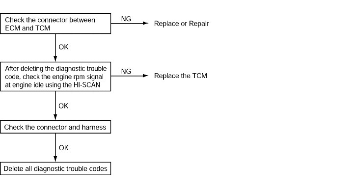
Code No. P0725 Malfunction of engine rpm signal line | Probable cause |
If no output pulse is detected for 5 seconds or more while driving at 1,000 rpm, it is judged that there is anopen and diagnostic trouble code No.P0725 is set. | ● Malfunction of connector ● Malfunction of the TCM ● No engine rpm signal from ECM |
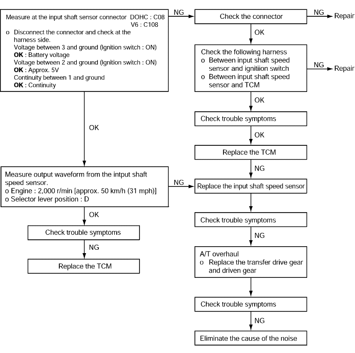
Code No. P0715 Input shaft speed sensor system | Probable cause |
If no output pulse is detected from the input shaft speed sensor for 1 seconds or more while driving in 3rd or 4th gear at a speed of 30 km/h (19 mph) or more, it is judged to be an open circuit or short circuit in the input shaft speed sensor and diagnostic trouble code No.P0715 is set. If diagnostic trouble code P0715 is set four times, the transaxle is locked into 3rd gear or 2nd gear as a fail-safe measure. | ● Malfunction of the input shaft speed sensor (PG-A) ● Malfunction of underdrive clutch retainer ● Malfunction of connector ● Malfunction of the TCM |
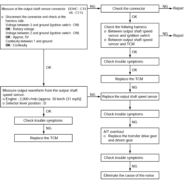
Code No. P0720 Output shaft sensor system | Probable cause |
If the output from the output shaft speed sensor is continuously 50% lower than the vehicle speed for 1 second or more, it is judged to be an open circuit or short circuit in the outputshaft speed sensor and diagnostic trouble code No.P0720 is set. | ● Malfunction of the output shaft speed sensor ● Malfunction of connector ● Malfunction of the TCM |
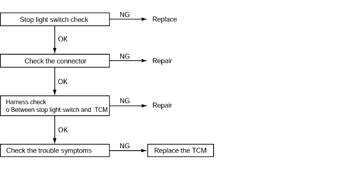
Code No.P0703 Stop light switch system | Probable cause |
If the stop light switch is on for 5 minutes or more while driving, it is judged that there is a short circuitin the stop light switch and diagnostic trouble code P0703 is set. | ● Malfunction of the stop light switch ● Malfunction of connector ● Malfunction of the TCM |
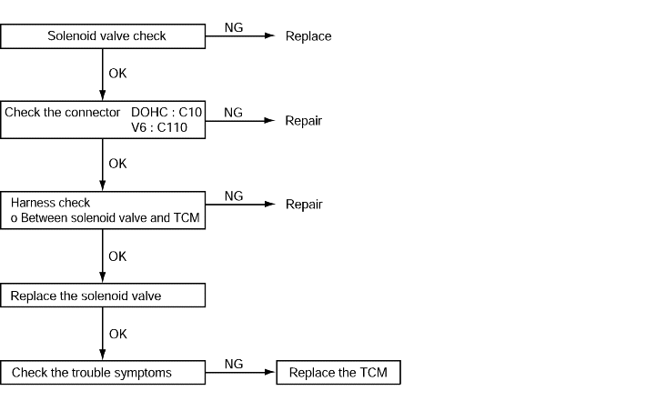
Code No.P0750 Low and reverse solenoid valve system | Probable cause |
Code No.P0755 Underdrive solenoid valve system | |
Code No.P0760 Second solenoid valve system | |
Code No.P0765 Overdrive solenoid valve system | |
If the resistance value for a solenoid valve is too large or too small, it is judged that there is a short circuit or an open circuit in the solenoid valve and the respective diagnostic trouble code is set. The transaxle is locked into 3rd gear as a fail-safe measure. | ● Malfunction of the solenoid valve ● Malfunction of connector ● Malfunction of the TCM |
Code No.P0743 /P0740 Torque converter clutch solenoid system | Probable cause |
If the resistance value for the torque converter clutch solenoid is too large or too small, it is judged that there is a short-circuit or an open circuit in the torque converter clutch solenoid and diagnostic trouble code No.P0743 is set. If the drive duty rate for the torque converter clutch solenoid is 100% for a continuous period of 4 seconds or more, it is judged that there is an abnormality in the torque converter clutch system and diagnostic trouble code No.P0740 is set. When diagnostic trouble code No.P0743 is set, the transaxle is locked into 3rd gear as a fail-safemeasure. If the lock-up clutch remains engaged for a continuous period of 10 seconds when the TCM is attempting to disengage the lock-up clutch, it is judged that the torque converter clutch is stuck on and diagnostic troublecode P0740 is set. | ● Malfunction of the torque converter clutch solenoid ● Malfunction of connector ● Malfunction of the TCM |
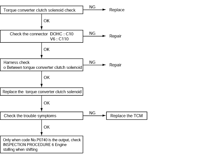
Code No.P0731 1st gear incorrect ratio | Probable cause |
If the output from the output shaft speed sensor multiplied by the 2nd gear ratio is not the same as the output from the input shaft speed sensor after the shifting to 2nd gear has been completed, diagnostic trouble code No.P0731 is set four times, and the transaxleis locked into 3rd gear as a fail-safe measure. | ● Malfunction of the input shaft speed sensor ● Malfunction of the output shaft speed sensor ● Malfunction of the underdrive clutch retainer ● Malfunction of the transfer drive gear or driven gear ● Malfunction of the second brake system ● Malfunction of the underdrive clutch system ● Noise generated |
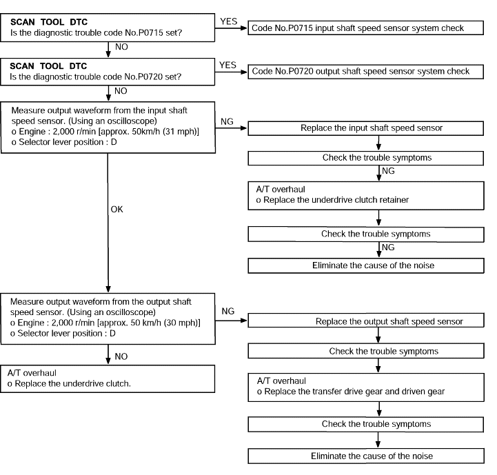
Code No.P0732 2nd gear incorrect ratio | Probable cause |
If the output from the output shaft speed sensor multiplied by the 2nd gear ratio is not the same as the output from the input shaft speed sensor after the shifting to 2nd gear has been completed, diagnostic trouble code No.P0732 is set. If diagnostic trouble code No.P0732 is set four times, the transaxle is locked into 3rd gear asa fail-safe measure. | ● Malfunction of the input shaft speed sensor ● Malfunction of the output shaft speed sensor ● Malfunction of the underdrive clutch retainer ● Malfunction of the transfer drive gear or driven gear ● Malfunction of the second brake system ● Malfunction of the underdrive clutch system ● Noise generated |
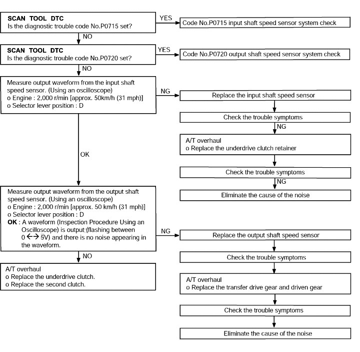
Code No.P0733 3rd gear incorrect ratio | Probable cause |
If the output from the output shaft speed sensor multiplied by the 3rd gear ratio is not the same as the output from the input shaft speed sensor after the shifting to 3rd gear has been completed, diagnostic trouble code No.P0733 is set. If diagnostic trouble code No.P0733 is set four times, the transaxle is locked into 3rd gear asa fail-safe measure. | ● Malfunction of the input shaft speed sensor ● Malfunction of the output shaft speed sensor ● Malfunction of the underdrive clutch retainer ● Malfunction of the transfer drive gear or driven gear ● Malfunction of the low and reverse brake system ● Malfunction of the underdrive clutch system ● Noise generated |
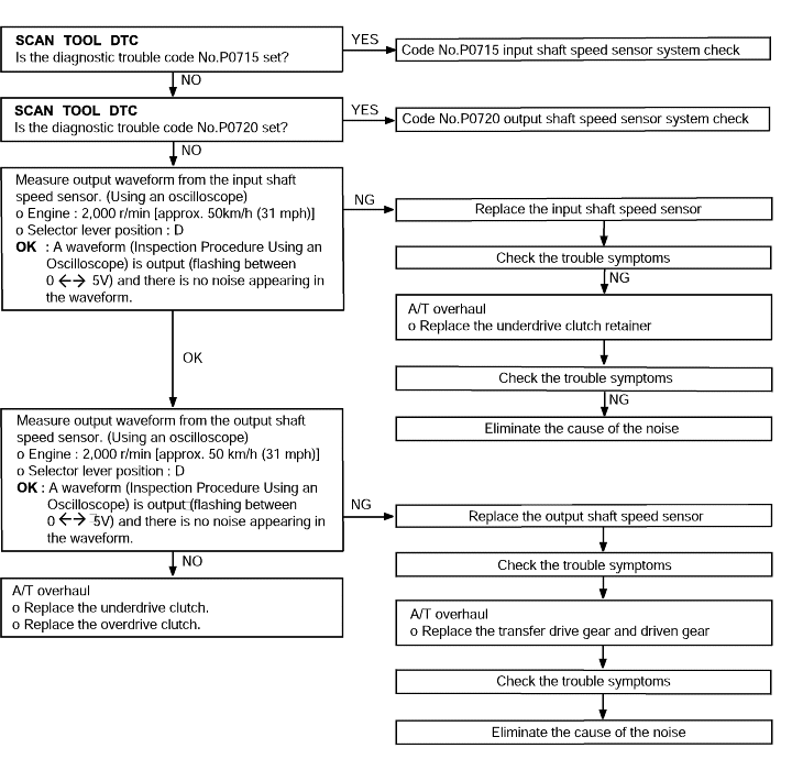
Code No.P0734 4th gear incorrect ratio | Probable cause |
If the output from the output shaft speed sensor multiplied by the 4th gear ratio is not the same as the output from the input shaft speed sensor after the shifting to 4th gear has been completed, diagnostic trouble code No.P0734 is set. If diagnostic trouble code No.P0734 is set four times, the transaxle is locked into 3rd gear asa fail-safe measure. | ● Malfunction of the input shaft speed sensor ● Malfunction of the output shaft speed sensor ● Malfunction of the underdrive clutch retainer ● Malfunction of the transfer drive gear or driven gear ● Malfunction of the low and reverse brake system ● Malfunction of the underdrive clutch systme ● Noise generated |
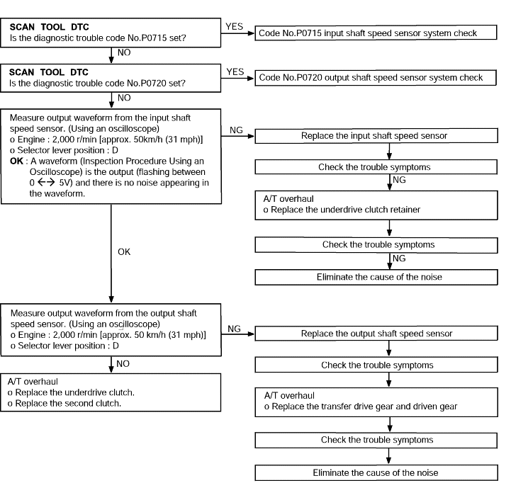
Code No.P0735 5th gear incorrect ratio | Probable cause |
If the output from the output shaft speed sensor multiplied by the 5th gear ratio is not the same as the output from the input shaft speed sensor after shifting to 4th gear has been completed, diagnostic trouble code No.P0735 is the output. If diagnostic trouble code No.P0735 is the output four times, the transaxle is locked into 3rd gear asa fail-safe measure. | - Malfunction of the input shaft speed sensor - Malfunction of the output shaft speed sensor - Malfunction of the direct clutch system - Malfunction of the direct planetary carrier - Malfunction of the overdrive clutch system - Malfunction of the direct clutch system - Noise generated |
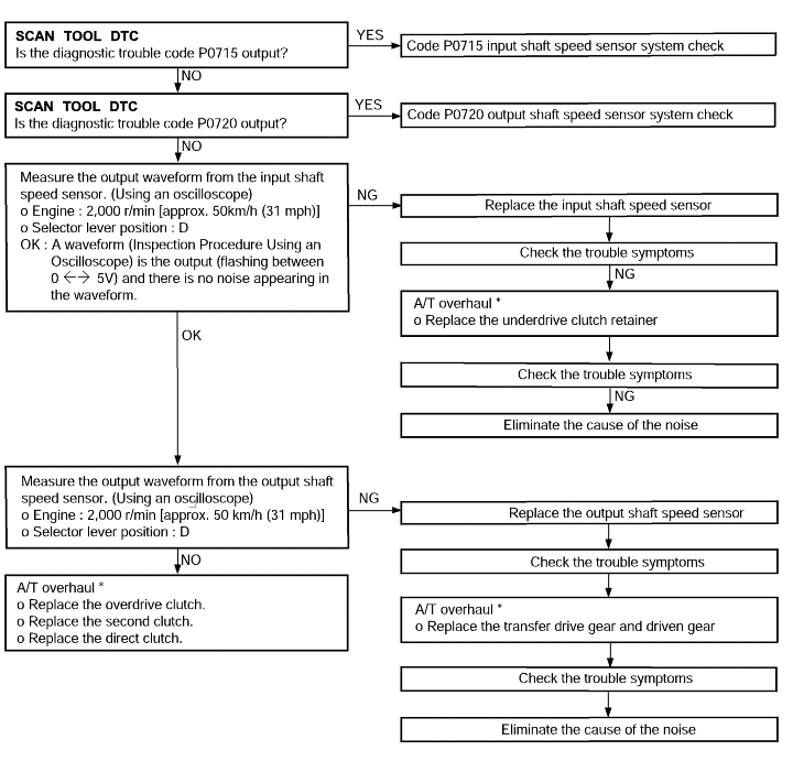
Code No.P0736 reverse gear incorrect ratio | Probable cause |
If the output from the output shaft speed sensor multiplied by the reverse gear ratio is not the same as the output from the input shaft speed sensor after the shifting to reverse gear has been completed, diagnostic trouble code No.P0736 is set. If diagnostic trouble code No.P0736 is set four times, the transaxle is locked into 3rd gear asa fail-safe measure | ● Malfunction of the input shaft speed sensor ● Malfunction of the output shaft speed sensor ● Malfunction of the underdrive clutch retainer ● Malfunction of the transfer drive gear or driven gear ● Malfunction of the low and reverse brake system ● Malfunction of the underdrive clutch systme ● Noise generated |
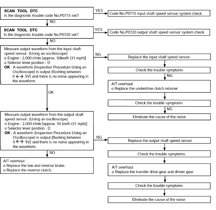
Code No.P1723 A/T Control relay system | Probable cause |
If the relay voltage is less than 7 V after the ignition switch has been turned to ON, it is judged that there is an open circuit or a short circuit in the A/T control relay ground and diagnostic trouble code P1723 is set. The transaxle is locked into 3rd gearas a fail-safe measure. | ● Malfunction of the A/T control relay ● Malfunction of connector ● Malfunction of the TCM |
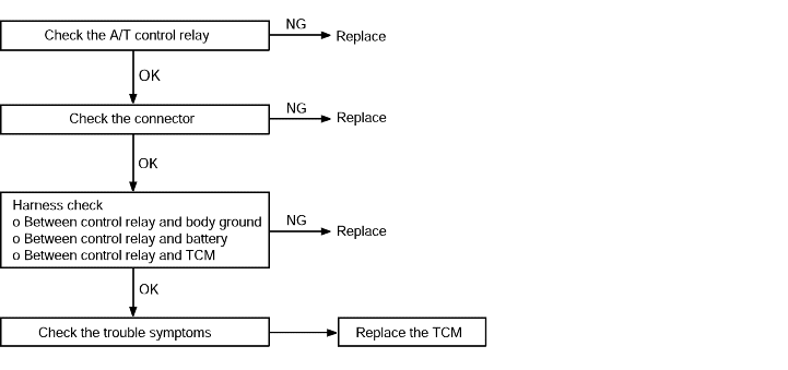
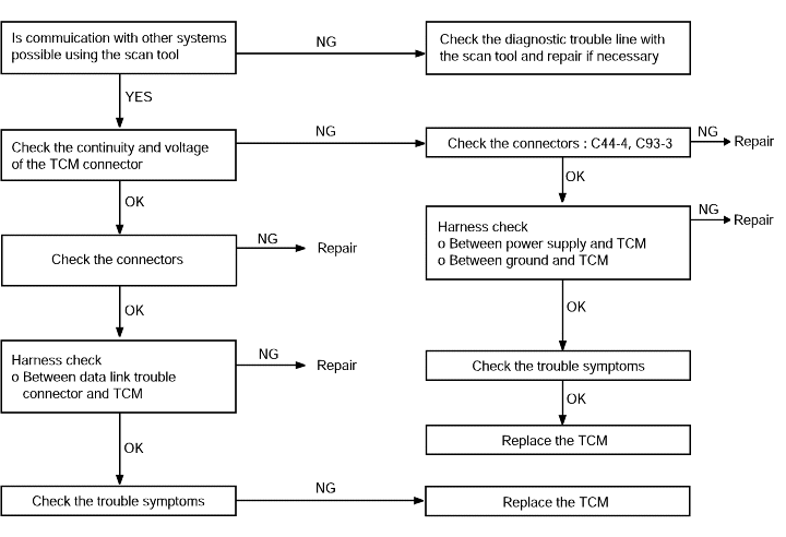
Communication with the scan tool | Probable cause |
If communication with a known good scan tool is not possible, the cause is probably a defective diagnostic troubleline or the TCM is not functioning. | ● Malfunction of diagnostic trouble line ● Malfunction of connector ● Malfunction of the TCM |
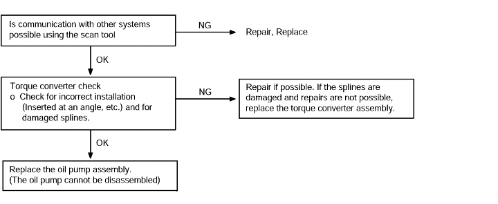
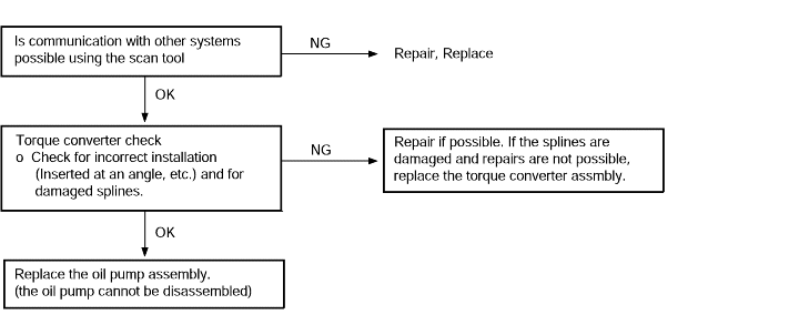
Starting impossible | Probable cause |
Starting is not possible when the selector lever is in P or N range. In such cases, the cause is possibly a defectiveengine system, torque converter or oil pump. | ● Malfunction of the engine system ● Malfunction of the torque converter ● Malfunction of the oil pump |
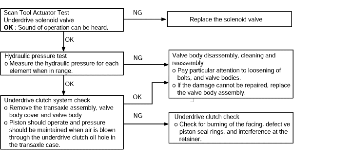
Does not move | Probable cause |
If the vehicle does not move forward when the selector lever is shifted from N to D range while the engine is idling, the cause is probably abnormal line pressure or a malfunction of the underdriveclutch or valve body. | ● Abnormal line pressure ● Malfunction of the underdrive solenoid valve ● Malfunction of the underdrive clutch ● Malfunction of the valve body |
Does not reverse | Probable cause |
If the vehicle does not reverse when the selector lever is shifted from N to R range while the engine is idling, the cause is probably abnormal pressure in the reverse clutch or low and reverse brake or a malfunction of the reverse clutch, low and reverse brake or valvebody. | ● Abnormal reverse clutch pressure ● Abnormal low and reverse brake pressure ● Malfunction of the low and reverse solenoid valve ● Malfunction of the reverse clutch ● Malfunction of the low and reverse brake ● Malfunction of the valve body |
Does not move (forward or reverse) | Probable cause |
If the vehicle does not move forward or reverse when the selector lever is shifted to any position while the engine is idling, the cause is probably abnormal line pressure, or a malfunctionof the power train, oil pump or valve body. | ● Abonormal line pressure ● Malfunction of the underdrive solenoid valve ● Malfunction of the underdrive clutch ● Malfunction of the valve body |

Engine stalling when shifting | Probable cause |
If the engine stalls when the selector lever is shifted from N to D or R range while the engine is idling, the cause is possibly a malfunction of the engine system, torque converter clutch solenoid,valve body or torque converter (torque converter clutch malfunction) | ● Malfunction of the engine system ● Malfunction of the torque converter clutch solenoid ● Malfunction of the valve body ● Malfunction of the torque converter (Malfunction of the torque converter clutch) |

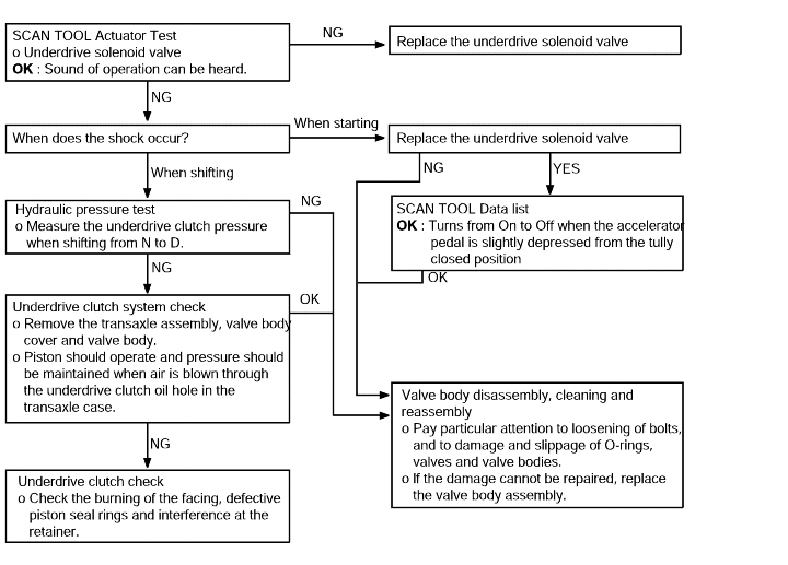
Shocks when changing from N to D range and time lag | Probable cause |
If abnormal shocks or a time lag of 2 second or more occur when the selector lever is shifted from N to D range while the engine is idling, the cause is probably abnormal underdrive clutchpressure or a malfunction of the underdrive clutch, valve body. | ● Abnormal line pressure ● Malfunction of the underdrive solenoid valve ● Malfunction of the underdrive clutch ● Malfunction of the valve body |
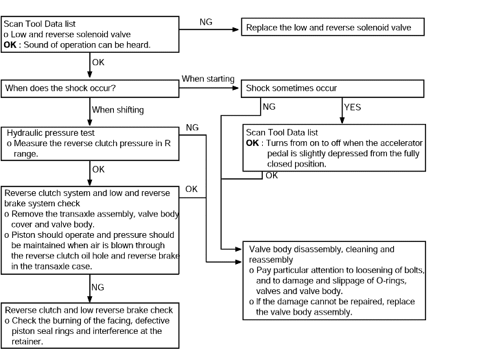
Shock when changing from N to R and large time lag | Probable cause |
If abnormal shocks or a time lag of 2 seconds or more occurs when the selector lever is shifted from N to R range while the engine is idling, the cause is probably abnormal reverse clutch pressure or low and reverse brake pressure, or a malfunction or the reverseclutch, low and reverse brake. | ● Abnormal reverse clutch pressure ● Abnormal low and reverse brake pressure ● Malfunction of the low and reverse solenoid valve ● Malfunction of the reverse clutch ● Malfunction of the low and reverse brake ● Malfunction of the valve body |
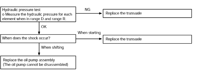
Shocks when changing from N to R, N to D and large time lag | Probable cause |
If abnormal shocks or a time lag of 2seconds or more occurs when the selector lever is shifted from N to R range while the engine is idling, the cause is probably abnormal line pressure ora malfunction of the oil pump or valve body. | ● Abnormal line pressure ● Malfunction of the oil pump ● Malfunction of the valve body |
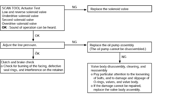
Shocks and running up | Probable cause |
If shocks occur when driving due to upshifting or downshifting and the transaxle speed becomes higher than the engine speed, the cause is probably abnormal line pressure or a malfunctionof a solenoid valve, oil pump, valve body, brake or clutch. | ● Abnormal line pressure ● Malfunction of each solenoid valve ● Malfunction of the oil pump ● Malfunction of the valve body ● Malfunction of brake or clutch |
All points (Displaced shifting points) | Probable cause |
If all shift points are displaced while driving, the cause is probably a malfunction of the output shaft speed sensor,TPS or a solenoid valve. | ● Malfunction of the output shaft speed sensor ● Malfunction of the throttle position sensor ● Malfunction of each solenoid valve ● Abnormal line pressure ● Malfunction of the valve body ● Malfunction of the TCM |
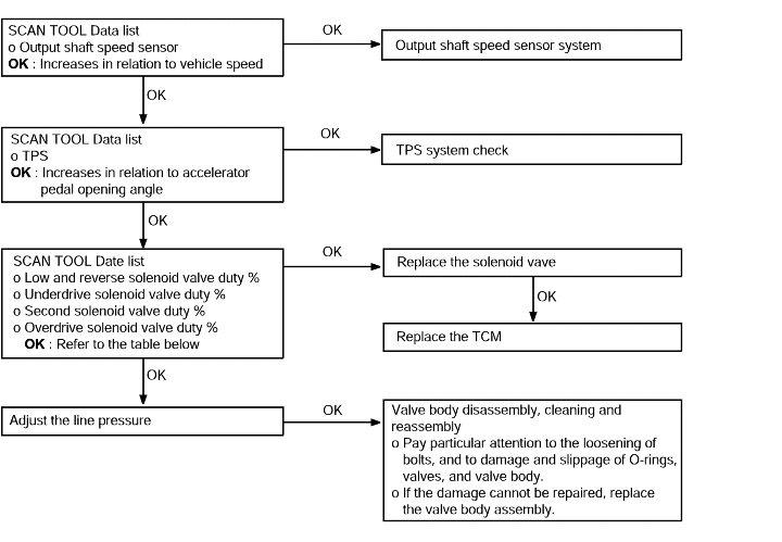
Some points (Displaced shifting points) | Probable cause |
If some of the shift points are displaced while driving, the cause is probably a malfunction of the valve body, or itis related to control and is not an abnormality. | ● Malfunction of the valve body |

No diagnostic trouble codes (Does not shift) | Probable cause |
If shifting does not occur while driving and no diagnostic trouble codes are output, the cause is probably a malfunctionof the Park/Neutral position switch, or TCM. | ● Malfunction of the Park/Neutral position switch ● Malfunction of the TCM |
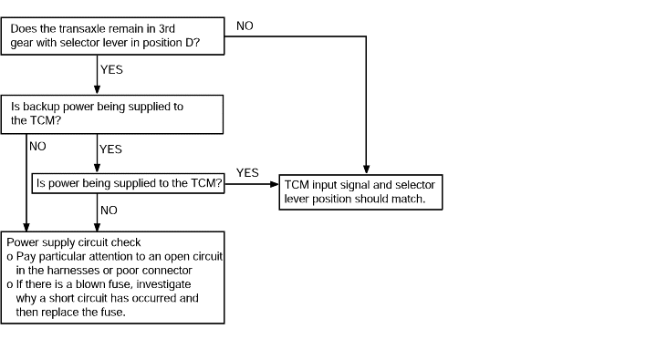
Poor acceleration | Probable cause |
If acceleration is poor even if downshifting occurs while driving, the cause is probably a malfunction of the engine system,brake or clutch. | ● Malfunction of the engine system ● Malfunction of brake or clutch |

Vibration | Probable cause |
If vibration occurs when driving at constant speed or when accelerating in top range, the cause is probably abnormal torque converter clutch pressure or a malfunction of the engine system, torqueconverter clutch solenoid, torque converter or valve body. | ● Abnormal torque converter clutch pressure ● Malfunction of the engine system ● Malfunction of the torque converter clutch solenoid ● Malfunction of the torque converter ● Malfunction of the valve body |
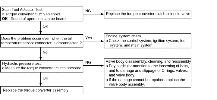
No | Condition | Operation | Judgement value | Check item |
1 | Ignition switch : OFF | Ignition switch (1) ON | Battery voltage (mV) | Control relay |
2 | ● Ignition switch : ON ● Engine : Stopped ● Select lever position : P | Selector lever position (1) P, (2) R, (3) N, (4) D | (1) P, (2) R, (3) N, (4) D | Transaxle range switch |
Accelerator pedal (1) Released (2) Half depressed (3) Depressed | (1) 400-1,000 mV (2) Gradually rises from (1) (3) 4,500-5,000 mV | Throttle position sensor | ||
Brake pedal (1) Depressed (2) Released | (1) ON (2) OFF | Stop lamp switch | ||
3 | ● Ignition switch : ST ● Engine : Stopped | Starting test with lever P or N range | Starting should be possible | Starting possible or impossible |
4 | Warming up | Drive for 15 minutes or more so that the automatic fluid temperature becomes 70-90°C | Gradually rises to 70-90°C | Oil temperature sensor |
5 | ● Engine : Idling ● Selector lever position : N | A/C switch (1) ON (2) OFF | (1) ON (2) OFF | Triple pressure switch |
Accelerator pedal (1) Released (2) Half depressed | (1) ON (2) OFF | Idle position switch | ||
(1) 600-925rpm (2) Gradually rises from (1) | ||||
(1) Data changes | Communication with engine-ECU | |||
Selector lever position (1) N → D (2) N →R | Should be no abnormal shifting shocks Time lag should be within 2 seconds | Malfunction when starting | ||
6 | Selector lever position : N (Carry out on a flat and straight road) | Selector lever position and vehicle speed 1. Idling in 1st gear (Vehicle stopped) 2. Driving at constant speed of 20 km/h in 1st gear 3. Driving at constant speed of 30 km/h in 2nd gear 4. Driving at 50 km/h in 3rd gear with accelerator fully closed 5. Driving at constant speed of 50 km/h in 4th gear (Each condition should be maintained for 10 seconds or more) | (2) 1st, (4) 3rd, (3) 2nd, (5) 4th | Shift condition |
(2) 0%, (4) 100%, (3) 100%, (5) 100% | Low and reverse solenoid valve | |||
(2) 0%, (4) 0%, (3) 0%, (5) 100% | Underdrive solenoid valve | |||
(2) 100%, (4) 100%, (3) 0%, (5) 0% | Second solenoid valve | |||
(2) 100%, (4) 0%, (3) 100%, (5) 0% | Overdrive solenoid valve | |||
(1) 0km/h (4) 50km/h | Vehicle speed sensor | |||
(4) 1,800-2,100rpm | Input shaft speed sensor | |||
(4) 1,800-2,100rpm | Output shaft speed sensor | |||
(3) 0% (5) Approx. 70-90% | Damper clutch control solenoid valve | |||
(3) Approx. 100-300rpm (5) Approx. 0-10rpm | ||||
7 | Seletor lever position : D (Carry out on a flat and straight road) | 1. Accelerate to 4th gear at a throttle position sensor output of 1.5V (accelerator opening angle of 30 %). 2. Gently decelerate to a standstill 3. Accelerate to 4th gear at a throttle position sensor output of 2.5 V (accelerator opening angle of 50%). 4. While driving at 60 km/h in 4th gear, shift down to 3rd gear 5. While driving at 40 km/h in 3rd gear, shift down to 2nd gear 6. While driving at 20 km/h in 2nd gear, shift down to 1st gear | For (1), (2) and (3), the reading should be the same as the specified output shaft torque, and no abnormal shocks should occur. For (4), (5) and (6), downshifting should occur immediately after the shifting operation is made. | Malfunction when shifting |
Displaced shift points | ||||
Does not shift | ||||
Does not shift from 1 to 2 or 2 to 1 | ||||
Does not shift from 2 to 3 or 2 to 3 | ||||
Does not shift from 3 to 4 or 4 to 3 | ||||
8 | Selector lever position : N (Carry out on a flat and straight road). | Move selector lever to R range drive at contant speed of 10 km/h | The ratio between input and output speed sensor data should be the same as the gear ratio when reversing. | Does not shift |
DTC No | Diagnosis item | Possible cause | |
P1704 | Throttle position sensor | Short circuit | TPS output > 4.8 V with engine idling |
P1703 | Open circuit | TPS output < 0.2V with engine not idling | |
P1702 | Sensor misadjustment | TPS output < 0.2V or > 1.2V with engine idling | |
P0713 | Fluid temperature sensor | Open circuit | Oil temperature sensor output > 4.57 V for 1 second or longer (oil temperature does not increase) |
P0712 | Short circuit | Output < 0.49V for 1 second | |
P0725 | Engine rpm signal line | Malfunction | No crank angle sensor output pulse detected for 5 seconds at 1,000 rpm |
P0715 | Input speed sensor | Short circuit/open circuit | No input speed sensor output pulse detected for > 1 second at vehicle speed of > 30 km/h |
P0720 | Output speed sensor | Short circuit/open circuit | At vehicle speed of > 30 km/h, output speed sensor output < 50% of vehicle speed sensor output for > 1 second |
P0703 | Stop lamp switch | Short circuit/open circuit | At vehicle speed of 6 km/h, stop lamp switch is ON continuously for 5 minutes |
P0750 | LR solenoid valve | Short circuit/open circuit | With relay voltage>10V, open or short circuit is continuously for 0.3 second |
P0755 | UD solenoid valve | Short circuit/open circuit | |
P0760 | 2nd solenoid valve | Short circuit/open circuit | |
P0765 | OD solenoid valve | Short circuit/open circuit | |
P0743 | TCC solenoid valve | Short circuit/open circuit | |
P0731 | Gear shift incomplete | 1st | After gear shift, output shaft speed sensor output x gear ratio of new gear≠ input shaft speed sensor output |
P0732 | 2nd | ||
P0733 | 3rd | ||
P0734 | 4th | ||
P0735 | 5th | ||
P0736 | Reverse | ||
P1749 | Serial communication | Short circuit/open circuit | With ignition ON, battery voltage > 10V, and engine speed > 450 r/min, communication is continuously irregular for 1 second or communication errorsignal is received for > 4 seconds continuously |
P0740 | TCC | System defect/stuck on | DCC solenoid valve drive duty ratio is 100% for 4 seconds continuously |
P1723 | A/T control relay | Earth short circuit/open circuit | After ignition ON, A/T control relay voltage < 7V |
P0707 | Transaxle range switch | Open circuit | No signal is continuous for > 30 seconds |
P0708 | Short circuit | Above 2 kinds signals are continuous for 30 seconds | |
P1630 | CAN-BUS OFF | TCM Fail/open/short | Receive BUS-OFF information from CAN CONTROLLER |
P1631 | CAN-TIME OUT ECM | ECM Fail/open/short | No output signal for 1.5 second |
P1764 | CAN MI-COM CIRCUIT | TCM internal circuit malfunction | Communication error output is continuously for > 1 second |
Code | Diagnosis item | Probable cause | |
P1704 | Throttle position sensor system If the TPS output voltage is 4.8 V or higher when the engine is idling, the output is judged to be too high and diagnosis code P1704 is set. If the TPS output voltage is 0.2 V or lower at times other than when the engine is idling, the output is judged to be too low and diagnosis code P1703 is set. If the TPS output voltage is 0.2 V or lower or if it is 1.2 V or higher when the engine is idling, the TPS adjustment is judged to be incorrect and diagnosiscode P1702 set. | Short circuit | ● Malfunction of the throttle position sensor ● Malfunction of connector ● Malfunction of the TCM |
P1703 | Open circuit | ||
P1702 | Sensor misadjusted | ||
P0713 | Fluid temperature sensor system If the fluid temperature sensor output voltage is 4.57 V or more even after driving for 10 minutes or more (if the fluid temperature does not increase), it is judged that there is an open circuit in the fluid temperature sensorand diagnosis code P0713 is set. | Open circuit Short circuit | ● Malfunction of the oil temperature sensor ● Malfunction of connector ● Malfunction of the TCM |
P0712 | |||
P0725 | Malfunction of engine rpm signal line If no engine rpm signal pulse is detected for 5 seconds or more while driving at 1,000 rpm, it is judged that there is an open or short circuitin engine rpm signal line and diagnosis code P0725 is set. | Open circuit | ● Malfunction of connector ● Malfunction of the TCM ● No engine rpm signal from ECM |
P0715 | Input speed sensor system If no output pulse is detected from the input shaft speed sensor for 1 second or more while driving in 3rd or 4th gear at a speed of 30 km/h or more, there is judged to be an open circuit or short. Circuit in the input shaft speed sensor and diagnosis code P0715 is set. If diagnosis code P0715 is set four times, the transmission is locked into 3rd gear (D range) or 2ndgear as a fail-safe measure. | Short circuit/open circuit | ● Malfunction of the input shaft speed sensor ● Malfunction of the underdrive clutch retainer ● Malfunction of connector ● Malfunction of the TCM |
P0720 | Output speed sensor system If the output from the output shaft speed sensor is continuously 50% lower than the vehicle speed for 1 second or more while driving in 3rd or 4th gear at a speed of 30 km/h or more, there is judged to be an open circuit or short-circuit in the output shaft speed sensor and diagnosis code P0720 is set. If diagnosis code P0720 is set four times, the transmission is lockedinto 3rd gear (D range) or 2nd gear as a fail-safe measure. | Short circuit/open circuit | ● Malfunction of the outputs shaft speed sensor ● Malfunction of connector ● Malfunction of the TCM ● Malfunction of the transfer drive gear or driven gear |
P0703 | Stop lamp switch system If the stop lamp switch is on for 5 minutes or more while driving, it is judged that there is a short circuit in the stop lamp switch and diagnosiscode P0703 is set. | Short circuit/open circuit | ● Malfunction of the stop lamp switch ● Malfunction of connector ● Malfunction of the TCM |
P0750 | Low and reverse solenoid valve system | Short circuit/Open circuit | ● Malfunction of solenoid valve ● Malfunction of connector ● Malfunction of the TCM |
P0755 | Underdrive solenoid valve system | Short circuit/Open circuit | |
P0760 | Second solenoid valve system | Short circuit/Open circuit | |
P0765 | Overdrive solenoid valve system If the resistance value for a solenoid valve is too large or too small, it is judged that there is a short circuit or an open circuit in the solenoid valve and the respective diagnosis code is set. The transmission is lockedinto 3rd gear as a fail-safe measure. | Short circuit/Open circuit | |
P0743 | Torque converter clutch solenoid valve system If the resistance value for a solenoid valve is too large or too small, it is judged that there is a short circuit or an open circuit in the solenoid valve and the respective diagnosis code is set. The transmission is lockedinto 3rd gear as a fail-safe measure. | Short circuit/Open circuit | ● Malfunction of the torque converter clutch solenoid valve ● Malfunction of connector ● Malfunction of the TCM |
P0740 | Defective system | ||
P0731 | 1st gear ratio does not meet the specification If the output from the output shaft speed sensor multiplied by the 1st gear ratio is not the same as the output from the input shaft speed sensor after the shift to 1st gear has been completed, diagnosis code P0731 is set. If diagnosis code P0731 is set four times, the transmission is locked into3rd gear as a fail-safe measure. | ● Malfunction of the input shaft speed sensor ● Malfunction of the output shaft speed sensor ● Malfunction of the underdrive clutch retainer ● Malfunction of the transfer drive gear or driven gear ● Malfunction of the low and reverse brake system ● Malfunction of the underdrive clutch system ● Noise generated | |
P0732 | 2nd gear ratio does not meet the specification If the output from the output shaft speed sensor multiplied by the 2nd gear ratio is not the same as the output from the input shaft speed sensor after the shift to 3rd gear has been completed, diagnosis code P0732 is set. If diagnosis code P0732 is set four times, the transmission is locked into3rd gear as a fail-safe measure. | ● Malfunction of the input shaft speed sensor ● Malfunction of the output shaft speed sensor ● Malfunction of the underdrive clutch retainer ● Malfunction of the transfer drive gear or driven gear ● Malfunction of the underdrive clutch system ● Malfunction of the second brake system ● Noise generated | |
P0733 | 3rd gear ratio does not meet the specification If the output from the output shaft speed sensor multiplied by the 3rd gear ratio is not the same as the output from the input shaft speed sensor after the shift to 3rd gear has been completed, diagnosis code P0733 is set. If diagnosis code P0733 is set four times, the transmission is locked into3rd gear as a fail-safe measure. | ● Malfunction of the input shaft speed sensor ● Malfunction of the output shaft speed sensor ● Malfunction of the underdrive clutch retainer ● Malfunction of the transfer drive gear or driven gear ● Malfunction of the underdrive clutch system ● Malfunction of the overdrive clutch system ● Noise generated | |
P0734 | 4th gear ratio does not meet the specification If the output from the output shaft speed sensor multiplied by the 4th gear ratio is not the same as the output from the input shaft speed sensor after the shift to 4th gear has been completed, diagnosis code P0734 is set. If diagnosis code P0734 is set four times, the transmission is locked into3rd gear as a fail-safe measure. | ● Malfunction of the input shaft speed sensor ● Malfunction of the output shaft speed sensor ● Malfunction of the underdrive clutch retainer (5A/T) ● Malfunction of the transfer drive gear or driven gear ● Malfunction of the second brake system (4A/T) ● Malfunction of the overdrive clutch system (4A/T, 5A/T) ● Noise generated ● Direct clutch (5A/T) | |
P0735 | 5th gear ratio does not meet the specification If the output from the output shaft speed sensor multiplied by the 5th gear ratio is not the same as the output from the input shaft speed sensor after the shift to 5th gear has been completed, diagnosis code P0735 is set. If diagnosis code P0735 is set four times, the transmission is locked into3rd gear as a fail-safe measure. | ● Malfunction of the input shaft speed sensor (5A/T) ● Malfunction of the output shaft speed sensor (5A/T) ● Malfunction of the overdrive clutch system (5A/T) ● Malfunction of the direct clutch (5A/T) ● Noise generated | |
P0736 | Reverse gear ratio does not meet the specification If the output from the output shaft speed sensor multiplied by the reverse gear ratio is not the same as the output from the input shaft speed sensor after the shift to reverse gear has been completed, diagnosis code P0736 is set. If diagnosis code P0736 is set four times, the transmission is lockedinto 3rd gear as a fail-safe measure. | ● Malfunction of the input shaft speed sensor ● Malfunction of the output shaft speed sensor ● Malfunction of the underdrive clutch retainer ● Malfunction of the transfer drive gear or driven gear ● Malfunction of the low and reverse brake system ● Malfunction of the reverse clutch system ● Noise generated | |
P1749 | Serial communication If normal communication is not possible for a continuous period of 1 second or more when the ignition switch is at the ON position, the battery voltage is 10 V or more and the engine speed is 450 r/min or more, diagnosis code No.P1749 is set. Diagnosis code No.P1749 is also set if the data being received is abnormal for a continuous period of 4 seconds under the same conditions. | ● Malfunction of connector ● Malfunction of the ECM ● Malfunction of the TCM | |
P1723 | A/T control relay system If the A/T control relay voltage is less than 7 V after the ignition switch has been turned ON, it is judged that there is an open circuit or a short-circuit in the A/T control relay ground and diagnosis code P1723 is set. Then the transmission is locked into 3rd gar as a fail-safe measure. | Short circuit to ground/ Open circuit | ● Malfunction of the A/T control relay ● Malfunction of connector ● Malfunction of the TCM |
P0707 | Transaxle range switch No signal is continuous for > 30 seconds | ● Malfunction of transaxle range switch | |
P0708 | Above 2 signals are continuous for > 30 seconds | ||
P1630 | CAN-BUS OFF ● No 3 speed hold fail ● No PG-A, B fail ● Battery voltage > 10V continuously for 0.5 second ● No engine stop ● Receive BUS OFF information from CAN CONTROLLER | ● TCM Fail ● TCM side open & short | |
P1631 | CAN-TIME OUT ECM ● No 3 speed hold fail ● No PG-A, B fail ● Battery voltage > 10V continuously for 0.5 second ● No engine stop ● No output signal for 1.5 second | ● ECM fail ● ECM side open & short | |
P1764 | TCM CAN MI-COM ● No 3 speed hold fail ● No PG-A, B fail ● Battery voltage > 10V continuously for 0.5 second ● No engine stop ● Communication error output is continuously for > 1 second | ● CAN MI-COM CIRCUIT | |
ITEM | UD | OD | 2ND | LR | REV | OWC | |
P | - | - | - | O | - | - | |
R | - | - | - | O | O | - | |
N | - | - | - | O | - | - | |
D | 1 | O | - | - | O | - | O |
2 | O | - | O | - | - | - | |
3 | O | O | - | - | - | - | |
4 | - | O | O | - | - | - | |
ITEM | UD | OD | 2ND | LR | REV | RED | DIR | OWC | OWC1 | |
P | - | - | - | O | - | O | - | - | - | |
R | - | O | - | O | O | O | - | - | - | |
N | - | - | - | O | - | O | - | - | - | |
D | 1 | O | - | - | O | - | O | - | O | O |
2 | O | - | O | - | - | O | - | O | O | |
3 | O | O | - | - | - | O | - | O | - | |
4 | O | O | - | - | - | - | O | - | - | |
5 | - | O | O | - | - | - | O | - | - | |
Operating element | Code | Function |
Underdrive clutch | UD | Connects input shaft to the underdrive sun gear |
Reverse clutch | REV | Connects input shaft and reverse sun gear |
Overdrive clutch | OD | Connects input shaft and overdrive planetary carrier |
Low-and-reverse brake | LR | Locks low-and-reverse annulus gear and overdrive planetary carrier |
Second brake | 2ND | Locks reverse sun gear |
Direct clutch | DIR | Connects direct sun gear and direct carrier |
Reduction brake | RED | Locks reverse sun gear |
Oneway clutch | OWC | Regulates rotative direction of direct sun gear |
Oneway clutch | OWC1 | Regulates rotative direction of low and reverse annulus gear |
ITEM | Solenoid valve | ||||
Shift range | LR | 2ND | UD | OD | DCC |
1 | OFF | ON | OFF | ON | OFF |
2 | ON | OFF | OFF | ON | OFF |
3 | ON | ON | OFF | OFF | ON |
4 | ON | OFF | ON | OFF | ON |
R | OFF | ON | ON | ON | OFF |
N, P | OFF | ON | ON | ON | OFF |
ITEM | Solenoid valve | |||||
Shift range | LR (DIR) | 2ND | UD | OD | RED | DCC |
1 | OFF (LR) | ON | OFF | ON | OFF | OFF |
2 | ON (LR) | OFF | OFF | ON | OFF | OFF |
3 | ON (DIR) | ON | OFF | OFF | OFF | OFF |
4 | OFF (DIR) | ON | OFF | OFF | ON | ON |
5 | OFF (DIR) | OFF | ON | OFF | ON | ON |
R | OFF (LR) | ON | ON | ON | OFF | OFF |
N, P | OFF (LR) | ON | ON | ON | OFF | OFF |
Standard value : 0-0.16 mm |
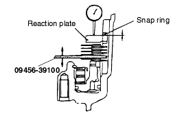
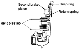
Standard value : 0.79 - 1.25 mm (2.0D, 2.5D) 1.09 - 1.55 mm (3.0D, 3.5D) |
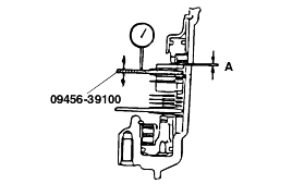
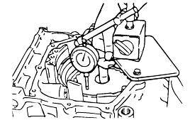
Standard value : 1.35 - 1.81 mm (2.0D) 1.65 - 2.11 mm (2.5D, 3.0D, 3.5D) |
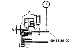
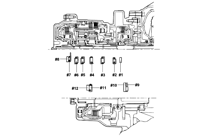
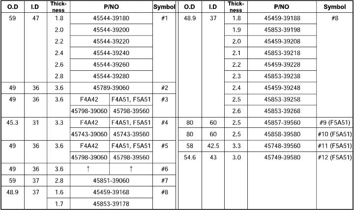
Standard value : 0.25-0.45 mm |
Installing the underdrive clutch hub makes it easy to measure the end play of the underdrive sun gear.
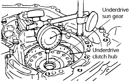
Standard value : (T+0.045 mm) to (T+0.105 mm) |
