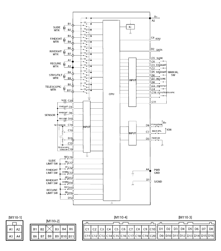
PIN NO.
PIN NAME
INPUT CONDITION
OUTPUT
A1
Recline motor front
Recline front switch ON
(Frontward)

A2
B+
Check for ENG. stop

A3
Recline motor rear
Recline front switch ON
(Rearward)

A4
Power ground
Ground lever compare to battery

B1
Slide motor (Front)
Slide front switch ON

B2
Slide motor (Rear)
Slide rear switch ON

B3
Front height motor (Up)
Front height up switch ON

B4
Front height motor (Down)
Front height down switch ON

B6
Rear height motor (Up)
Rear height up switch ON

B7
Rear height motor (Down)
Rear height down switch ON

C1
Front height manual switch
(Up)
Front height switch ON
(Upward)

C2
Front height manual switch
(Down)
Front height switch ON
(Downward)

C5
Slide manual switch (Front)
Slide switch ON (Frontward)

C6
Slide manual switch (Rear)
Slide switch ON (Rearward)

C7
Back up lamp
Shift lever "R" position

C8
IGN2 switch
IGN2 switch ON

C9
Front height position sensor
Front height operating when
IGN switch ON

C11
Manual switch common
B+

C12
Front limit switch (Up)
Front height moving to up limit

C13
Front limit switch (Down)
Front height moving to down limit

C16
Slide limit switch (Front)
Sliding to front limit

C17
Slide limit switch (Rear)
Sliding to rear limit

C19
Seat position sensor ground
IGN ON

C20
Slide position sensor
Sliding when IGN switch ON

D1
Signal ground
Ground

D2
IMS Data
Communication line
Pulse
D3
Parking brake
Parking brake switch ON

D4
"P" Position
Shift lever "P" Position

D5
Recline manual switch
(Up)
Recline switch ON
(Rear up)

D6
Recline manual switch
(Down)
Recline switch ON
(Rear down)

D7
Recline manual switch
(Front)
Recline switch ON
(Frontward)

D8
Recline manual switch
(Rear)
Recline switch ON
(Rearward)

D9
Rear height position
Rear height operating when IGN ON

D10
Recline position sensor
Reclining when IGN ON

D12
Limit switch common
B+

D13
Rear height limit switch
(Up)
Rear height to up limit

D14
Rear height limit switch
(Down)
Rear height to down limit

D15
Recline limit switch (Front)
Reclining to front limit

D16
Recline limit switch (Rear)
Reclining to rear limit


