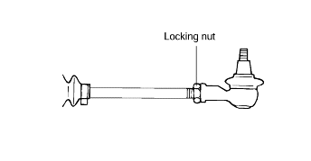
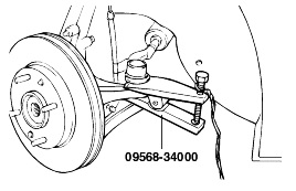
Using the special tool (09568-31000), disconnect the tie rod end from the knuckle arm.
Drain the power steering fluid.
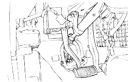
Remove the joint assembly connecting bolt.
Using the special tool (09568-31000), disconnect the tie rod end from the knuckle arm.

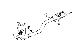
Discoonect the front muffler temporarily.
Remove the connecting bolts of front and rear roll stopper.
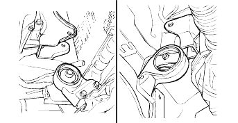
Remove the mounting bolts(6EA) of cross member complete assembly.
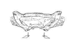
Disconnect the pressure hose and the retrun tube.
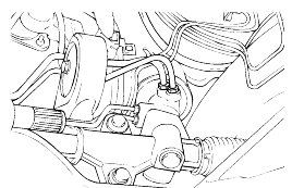
Remove the steering gear box mounting bolts and remove the steering gear box assembly and the mounting rubber.
When removing the gear box, pull it out carefully and slowly to avoid damaging the boots.
Remove the stabilizer bar.
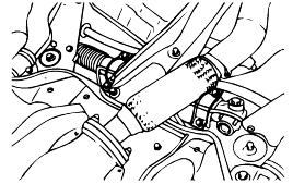
Remove the tie rod end from the tie rod.
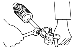
Remove the dust cover from the ball joint.
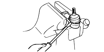
Remove the bellows band.
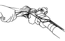
Remove the bellows clip.
Pull the bellows out toward the tie rod.
Check for rust on the rack when the bellows are replaced.
Remove the feed tube from the gear housing.
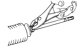
While moving the rack slowly, drain the fluid from the gear housing.
Unstake the tab washer which fixes the tie rod and rack with a chisel.
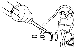
Remove the tie rod from the rack.
Remove the tie rod from the rack, taking care not to twist the rack.
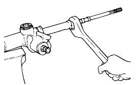
Remove the yoke plug lock nut.
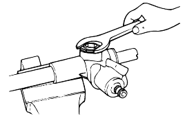
Using the special tool (09565-31300), remove the yoke plug.
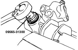
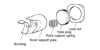
Remove the rack support spring, yoke support and bushing from the gear box.
Remove the end plug self-locking nut.
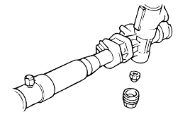
Detach the dust seal.
Remove the snap ring with snap ring pliers.
Remove the pinion and valve assembly and the oil seal (upper) using a soft hammer.
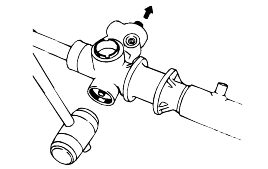
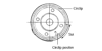
Turn the rack stopper clockwise until the end of the circlip comes out of the slot in the gear housing.
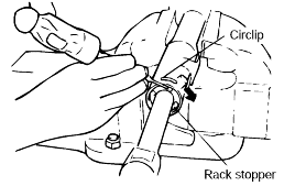
When the end of the circlip comes out from the notched hole of the housing rack cylinder, turn the rack stopper counter clockwise and removethe circlip.
Do not damage the rack when disassemble.
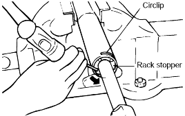
Remove the rack stopper, rack bushing and rack from the gear housing by moving them toward the piston side.
When the rack has been removed, be sure to replace the housing side oil seal with a new one.
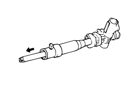
Remove the O-ring from the rack bushing.
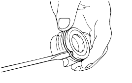
Remove the oil seal from the rack bushing.
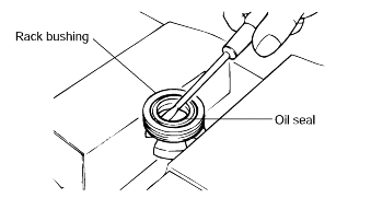
Remove out the ball bearing from the gear hausing using special tool(09517-21400)and hammer.
Do not damage the pinion valve cylinder inside of the gear housing.
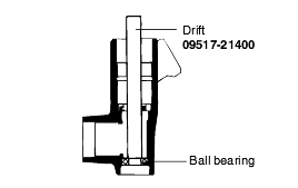
Remove out the needle bearing and oil seal.
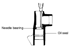
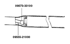
Use the special tools(09555-33100)to remove the back washer and oil seal from the gear housing.
Do not damage the rack cylinder inside of the gear housing.
Rack
Check for rack tooth face damage or wear
Check for oil seal contact surface damage or wear
Check for bending or twisting of rack
Check for oil seal ring damage or wear
Check for oil seal damage or wear
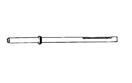
Pinion valve
Check for pinion gear tooth face damage or wear
Check for oil seal contact surface damage
Check for seal ring damage or wear
Check for oil seal damage or wear
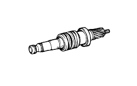
Bearing
Check for seizure or abnormal noise during bearing rotation
Check for excessive play
Check for missing needle bearing rollers
Others
Check for damage of the gear housing cylinder bore
Check for boot damage, cracking or ageing
Apply the specified fluid to the entire surface of the oil seal and gear housing.
Recommended fluid Power steering fluid (PSF-3) |
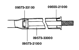
Using the special tools (09555-21000, 09573-21000, 09573-33000, 09573-33100), install the backup washer and oil seal to the specified positionin the gear housing.
Apply the specified grease to the entire surface of the needle bearing.
Recommended grease Multipurpose grease SAE J310a, NLGI No.2 |
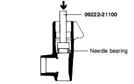
Install the needle bearing in the gear housing using the special tool(09222-21100).
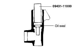
Set the scribed side of the oil seal (inner) in the special tool(09431-11000)and install in the gear housing.
Note the direction of the oil seal.
Use a new oil seal.
Apply the specified fluid to the entire surface of the rack bushing oil seal.
Recommended fluid Power steering fluid (PSF-3) |
Install the oil seal on the rack bushing.
Apply the specified fluid to the entire surface of the O-ring and install to the rack bushing using the special tool (09431-11000).
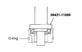
Apply the specified grease to the rack teeth.
Recommended grease Multipurpose grease SAE J310a, NLGI grade #2 EP |
Do not plug the vent hole in the rack with grease.
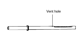
Insert the rack into the gear housing. Install the rack bushing and rack stopper.
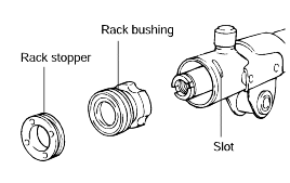
Push in the rack stopper until the circlip groove of the rack stopper is aligned with the notched hole of the rack housing and then install thecirclip while turning the rack stopper.
The circlip end should not be visible through the notched hole of the rack housing.
Apply the specified fluid and grease to the pinion valve assembly and install to the gear housing assembly.
Recommended fluid Power steering fluid (PSF-3) |
Recommended grease Multipurpose grease SAE J310a, NLGI #2 EP |
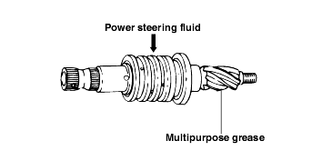
Install the ball bearing using the special tool (09222-21100).
Install the pinion and valve assembly to the valve housing.
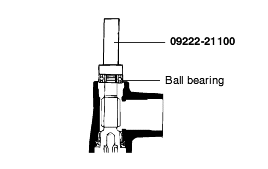
Install the oil seal using the special tool (09432-21601).
Install the snap ring with snap ring pliers.
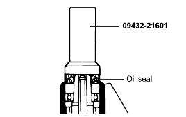
With the pinion turned all the way clockwise, tighten the self-locking nut.
Always replace the self-locking nut with a new one.
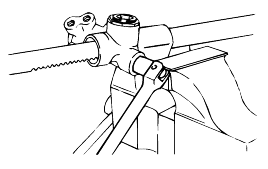
Apply semi-drying sealant to the threaded section of the end plug and tighten to the specified torque.
Tightening torque 50-70 Nm (500-700 kg·cm, 36-51 lb·ft) |
Stake the end plug at two points on its circumference with a punch.
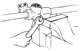
Install the tab washer and then the tie rod and hammer the tab washer end at two points to the tie rod.
Align the tab washer pawIs with the rack grooves.
Use a new tab washer.
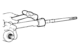
Install the bushing, rack support, yoke support spring and rack pluge in the order shown. Apply semi-drying sealant to the threaded sectionof the yoke pluge support cover before installation.

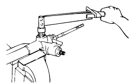
With the rack placed at the center position, attach the yoke plug to the gear housing. Tighten the yoke plug within the range of 20-25 Nm (200-250 kg.cm, 14.5-18 lb.ft), using the special tool. Loosen the yoke plug for approximately20° and tighten the locking nut to the standard value.
Stadard value Total pinion torque : 0.6-1.3Nm(6-13kg·cm, 0.4-0.9 lb·ft) |
After adjusting, install the yoke plug with lock nut.
When it cannot be adjusted within the specified return angle, check rack support plug components or replace.
Tighten the feed tube to the specified torque and install the mounting rubber with adhesive.
Apply the specified grease to the bellows mounting position (fitting groove) of the tie rod.
Recommended grease Multipurpose grease SAE J310a, NLGI #2 EP |
Install the new attaching band to the bellows.
Whenever the bellows are installed, a new band must be used.
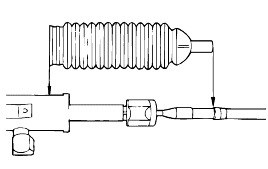
Install the bellows in, taking care not to twist it.
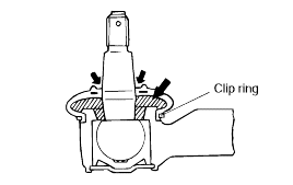
Fill the dust cover inner side and lip with the specified multipurpose grease, and place the dust cover in position with the clip ring attached inthe groove of the tie rod end.
Recommended grease Multipurpose grease SAE J310a, NLGI #2 EP |
Install the tie rods so that the length of the left and right tie rods equals the standard value.
