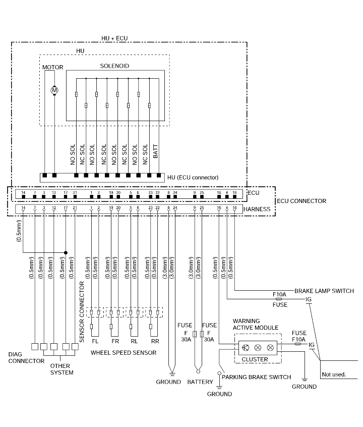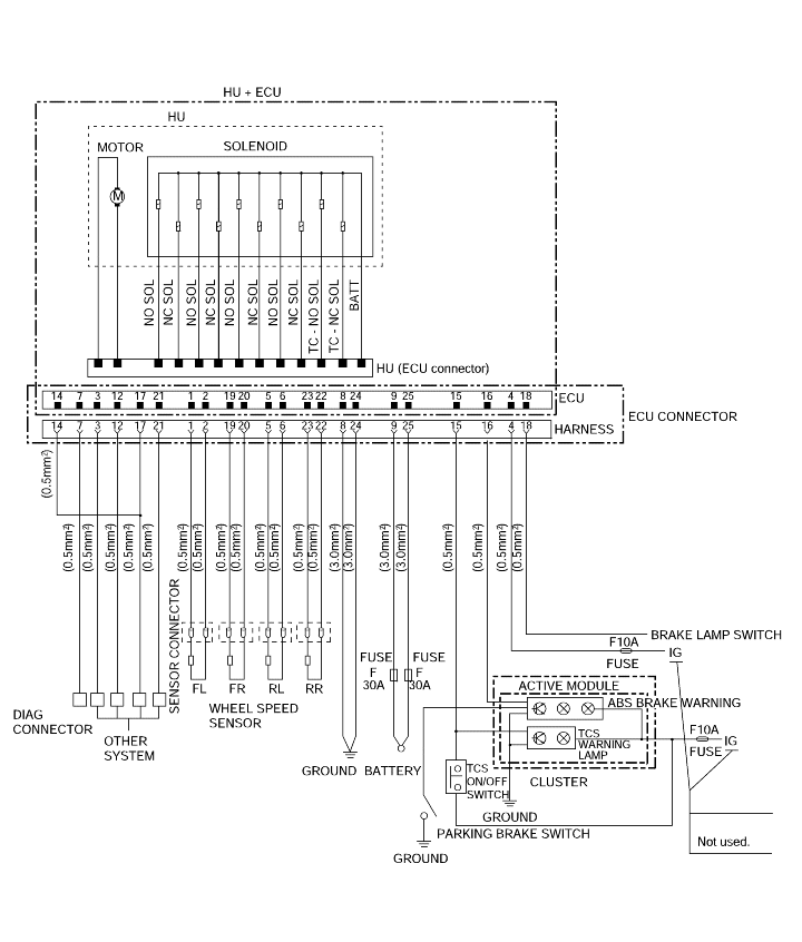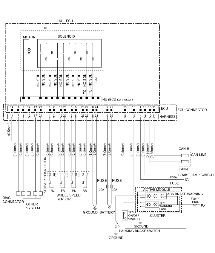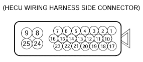


Connector terminal | Specification | Note | ||
No. | Mark | Terminal name | ||
4 | IGN+ | Power source via ignition switch terminal | Over voltage range : 16.5 ± 0.5V < V < 20V Operating voltage range : 9.5 ± 0.5V <V < 16.5 ± 0.5V Low voltage range : 7.0 ± 0.5V < V < 9.5 ± 0.5V System down range : V < 5.5 ± 0.5V Max. current : I < 300mA | |
8 24 | GND1 GND2 | Ground terminal | Max. current : I < 60A | In ABS control |
18 | BRAKE | Brake lamp switch input terminal | < 2.75V < 16.00V | |
1 19 5 23 2 20 6 22 | FL+ FR+ RL+ RR+ FL- FR- RL- RR- | Wheel sensor input terminal | > 150mV Resistance : 1,385 ± 110Ω | |
16 | WLP | ABS and EBD warning lamp output terminal | Max. current : I < 200mA < 1.5V | |
7 | Diag. | Diagnosis interface terminal | V V | : Ignition voltage |
3 | FR-out | Wheel speed output terminal | ||
9 | Batt 1 | Battery power Source 1 terminal (Valve power source) | System voltage | |
25 | Batt 2 | Battery power Source 2 terminal (Motor power source) | System voltage Max. rush current : I < 100A (t < 100 msec) Max. current : I < 30A (t > 100 msec) | t : The running time of motor |
14 | ECU check pin | ECU check pin | ||
15 | TCS Lamp | TCS Warning/Function lamp output | Max. current : I < 200mA | With TCS |
10 | CAN_L | CAN Bus line (Low) | Max. current : I < 10mA | With TCS |
11 | CAN_H | CAN Bus line (High) | Max. current : I < 10mA | With TCS |