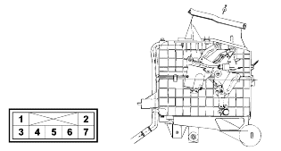
2.
Mode actuator circuit diagram and voltage

Terminal | Description | Voltage |
1 | IG | 12V |
2 | Ground | - |
3 | Vent | 0V |
4 | Bi-level | 12V |
5 | Floor | 12V |
6 | Mix | 12V |
7 | Defroster | 12V |
Pressing the mode select switch with the ignition on will shift the driver side and passenger side mode door actuators as follows :
VENT ⇒ BI/LEVEL ⇒ FLOOR ⇒ MIX
Mode actuator circuit diagram and voltage

Terminal | Description | Voltage |
1 | IG | 12V |
2 | Ground | - |
3 | Vent | 0V |
4 | Bi-level | 12V |
5 | Floor | 12V |
6 | Mix | 12V |
7 | Defroster | 12V |
Mode | Recirculation | Fresh | |||
COOL | 1/2 COOL | WARM | |||
Position | Vent | Bi level | Floor | Mix | Defroster |
Vent | 100% | 55 ± 10% | - | - | - |
Floor | - | 45 ± 10% | 54 ± 5% | 42.9 ± 7% | - |
Defroster | - | - | 18 ± 5% | 35.1 ± 7% | 72% |
Side vent | - | - | 28 ± 4% | 22 ± 4% | 28 ± 4% |
Mode | Recirculation | Fresh | |||
COOL | 1/2 COOL | WARM | |||
Position | Vent | Bi level | Floor | Mix | Defroster |
Vent | 86.5 ± 5% | 52 ± 10% | - | - | - |
Floor | - | 39.5 ± 10% | 49.5 ± 5% | 42.9 ± 7% | - |
Defroster | - | - | 16.5 ± 5% | 35.1 ± 7% | 72 ± 7% |
Side vent | - | - | 18.5 ± 4% | 22 ± 4% | 28 ± 4% |
Rear vent | 13.5 ± 5% | 8.5 ± 5% | 15.5 ± 5% | - | - |