SPECIFICATIONS

Description

Specification

Limit

General

Type

3.5/3.0

Number of cylinders

3.5/3.0

Bore

3.5

3.0

Stroke

3.5

3.0

Total displacement

3.5

3.0

Compression ratio

3.5 / 3.0

Firing order

3.5 / 3.0

V-type, DOHC

6

93.0 mm (3.661 in.)

91.1 mm (3.587 in.)

85.8 mm (3.3779 in.)

76.0 mm (2.992 in.)

3497 cc

2972 cc

10.0

1 - 2 - 3 - 4 - 5 - 6

Valve timing

Intake valve

Opens (BTDC)

3.5

3.0

Closes (ABDC)

3.5

3.0

Exhaust valve

Opens (BBDC)

3.5

3.0

Closes (ATDC)

3.5

3.0

Valve overlap

3.5/3.0

Intake valve duration

3.5/3.0

Exhaust valve duration

3.5/3.0

11.5°

16.5°

60.5°

55.5°

43.5°

48.5°

20.5°

15.5°

32°

252°

244°

Camshaft

Drive mechanism

3.5/3.0

Cam height intake

3.5

3.0

Cam height exhaust

3.5/3.0

Journal diameter

3.5/3.0

Bearing oil clearance

3.5/3.0

End play

3.5/3.0

Cogged type belt

35.098 - 35.298 mm (1.3818 - 1.3897 in.)

34.81 - 35.01 mm (1.3705 - 1.3783 in.)

34.81 - 35.01 mm (1.3705 - 1.3783 in.)

25.951 - 25.970 mm (1.0220 - 1.0224 in.)

0.05 - 0.09 mm (0.0007 - 0.0024 in.)

0.1 - 0.15 mm (0.0039 - 0.0059 in.)

Cylinder head

Flatness of gasket surface

3.5/3.0

Flatness of maunting

Surface

Intake

3.5/3.0

Exhaust

3.5/3.0

Valve guide hole diameter

0.05 (0.002) O.S.

3.5/3.0

0.25 (0.010) O.S.

3.5/3.0

0.50 (0.020) O.S.

3.5/3.0

Intake valve seat ring hole diameter

0.3 (0.012) O.S.

3.5/3.0

0.6 (0.024) O.S.

3.5/3.0

Exhaust valve seat ring hole diameter

0.3 (0.012) O.S.

3.5/3.0

0.6 (0.024) O.S.

3.5/3.0

Max. 0.03 mm (0.0012 in.)

Max. 0.10 mm (0.0039 in.)

Max. 0.15 mm (0.0059 in.)

12.05 - 12.068 mm (0.474 - 0.475 in.)

12.25 - 12.268 mm (0.482 - 0.483 in.)

12.50 - 12.518 mm (0.492 - 0.493 in.)

36.30 - 36.325 mm (1.429 - 1.430 in.)

36.60 - 36.625 mm (1.441 - 1.442 in.)

33.30 - 33.325 mm (1.311 - 1.312 in.)

33.60 - 33.625 mm (1.323 - 1.324 in.)

0.05 mm

0.10 mm

0.15 mm

Valve

Overall length

Intake

Exhaust

Stem diameter

Intake

Exhaust

Face angle

Margin

Intake

Exhaust

Clearance (stem-to - guide)

Intake

Exhaust

106.28 mm (4.184 in.)

105.4 mm (4.150 in.)

6.565 - 6.580 mm (0.258 - 0.259 in.)

6.530 - 6.550 mm (0.257 - 0.258 in.)

45° - 45.5°

1.0 mm (0.0394 in.)

1.5 mm (0.059 in.)

0.02 - 0.05 mm (0.0009 - 0.0020 in.)

0.05 - 0.085 mm (0.0020 - 0.0033 in.)

105.78 mm (4.164 in.)

104.9 mm (4.130 in.)

0.5 mm (0.0197 in.)

1.0 mm (0.039 in.)

0.1 mm (0.0039 in.)

0.15 mm (0.0059 in.)

Valve spring

Free height

Lode

Out of squareness

46.4 mm (1.8268 in.)

24.0 kg / 37.9 mm (53 lb / 1.492 in.)

Max 2°

45.4 mm (1.787 in.)

Valve guide

Length

Intake

Exhaust

Service oversize

Valve seat contact width

Intake

Exhaust

Service oversize

Seat angle

Intake

Exhaust

45.5 mm (1.7913 in.)

50.5 mm (1.9882 in.)

0.05, 0.25, 0.50

0.9 - 1.3 mm (0.035 - 0.051 in.)

0.9 - 1.3 mm (0.035 - 0.051 in.)

0.30, 0.60

20°

45°

Piston

Diameter (Standard)

3.5

3.0

Clearance (Piston-to-cylinder)

3.5/3.0

Ring groove width

No. 1

3.5

3.0

No. 2

3.5/3.0

Oil

3.5/3.0

Piston for service

3.5/3.0

92.96 - 92.99 mm (3.659 - 3.661 in.)

91.06 - 91.09 mm (3.585 - 3.586 in.)

0.03 - 0.05 mm (0.0012 - 0.0020 in.)

1.503 - 1.505 mm (0.0592 - 0.05925 in.)

1.202 - 1.204 mm (0.0473 - 0.0474 in.)

1.501 - 1.503 mm (0.0591 - 0.0592 in.)

3.010 - 3.035 mm (0.1185 - 0.132 in.)

0.25 mm (0.010 in.), 0.50 mm ( 0.020 in.)

0.75 mm (0.030 in.), 1.00 mm ( 0.040 in.) Oversize

Piston ring

Number of rings per piston

Compression ring type

Oil ring

Compression ring type

No. 1

No. 2

Oil ring type

Ring end gap

No. 1

No. 2

Oil ring side rail

Ring side clearance

No. 1

No. 2

Ring for service

3

2

1

Barrel type, steel

Taper type, special cast iron

3-piece type

0.30 - 0.45 mm (0.0118 - 0.0177 in.)

0.45 - 0.60 mm (0.0177 - 0.0236 in.)

0.2 - 0.7 mm (0.0079 - 0.0276 in.)

0.04 - 0.08 mm (0.0016 - 0.0031 in.)

0.02 - 0.06 mm (0.0008 - 0.0024 in.)

0.25mm (0.010 in.), 0.50 mm (0.020 in.)

0.75 mm (0.030 in.), 1.00 (0.039 in.), Oversize

Connecting rod

Piston pin press - in load

Side clearance (Big end)

Bend

Twist

Bearing

Oil clearance

Pin diameter

7500 - 17,500 N (750 - 1,750 kg, 1,653 - 3,858 lb)

0.10 - 0.25 mm (0.0039 - 0.0098 in.)

0.05 mm or less/100 mm (0.0020 in. or less/3.937 in.)

0.1 mm or less/100 mm (0.0039 in. or less/3.937 in.)

0.022 - 0.048 mm (0.0009 - 0.002 in.)

21.974 - 21.985 mm (0.8651 - 0.8655 in.)

0.1 mm (0.004 in.)

Crankshaft

Journal O.D.

3.5

3.0

Pin O.D.

3.5

3.0

Out - of - roundness of journal and pin

3.5/3.0

Taper of journal and pin

3.5/3.0

End play

3.5/3.0

Main bearing

Oil clearance

3.5/3.0

63.982 - 64.00 mm (2.519 - 2.5197 in.)

59.978 - 59.996 mm (2.36 - 2.362 in.)

54.982 - 55.00 mm (2.165 - 2.1653 in.)

49.976 - 49.996 mm (1.967 - 1.968 in.)

Max. 0.03 mm (0.0012 in.)

Max. 0.005 mm (0.0002 in.)

0.05 - 0.25 mm (0.002 - 0.0098 in.)

0.018 - 0.036 mm (0.0007 - 0.0014 in.)

0.3 mm (0.012 in.)

Cylinder block

Cylinder bore

3.5

3.0

Flatness of gasket surface

3.5/3.0

Out - of - roundness and taper

3.5/3.0

93 mm (3.661 in.)

91.1 mm (3.586 in.)

Max. 0.05 mm (0.002 in.)

Max. 0.02 mm (0.0008 in.)

0.05 mm (0.002 in.)

Oil pump

Side clearance

Body clearance

Side clearance

Tip clearance

0.100 - 0.181 mm (0.0039 - 0.0071 in.)

0.040 - 0.095 mm (0.0016 - 0.0037 in.)

0.06 - 0.018 mm (0.0024 - 0.0071 in.)

Relief spring

Free length

Load

46.3 mm (1.823 in.)

3.4 kg/39.1 mm (7.5 lb. 1.54 in.)

Oil filter

Type

Cartridge, full flow

Engine oil pressure

80 kPa (11.4 psi) or more

[Conditions : Oil temperature is 75 to 90°C (167 to 194°F)]

Cooling method

Engine coolant cooling, forced circulation with electric fan

Cooling system

Quantity

8.2 lit (8.61 U.S.qts., 7.2 lmp.qts)

Thermostat

Type

Normal opening temperature

Opening temperature range

Wide open temperature

Wax pellet type with jiggle valve

82°C (179.6°F)

80°C - 84°C (176 - 183.2°F)

95°C (203°F)

Radiator cap

Main valve opening pressure

Main valve closing pressure

Vacuum valve opening pressure

86.1 - 124.5 kPa

(0.98 - 1.27 kg/cmk, 13.94 - 18.06 psi)

83.4 kPa (0.85 kg/cmk, 12.1 psi)

- 6.86 kPa (- 0.07 kg/cm², - 1.00 psi)

Air cleaner

Type

Element

Dry type

Unwoven cloth type

Exhaust pipe

Muffler

Suspension system

Expansion resonance type

Rubber hangers

SERVICE STANDARD

Stanard value

Coolant concentration

Tropical area : 40%

Other area : 50%

LUBRICANT

Engine coolant

Ethylene glycol base for aluminum radiator

SEALANT

Engine coolant temperature sensor

Three bond No.2310 or equivalent

LOCTITE 962T or equivalent

TIGHTENING TORQUE

Nm

kg.cm

lb.ft

Crankshaft bolt

Timing belt tensioner

Comshaft sprocket bolt

Cylinder head cover bolts

Main bearing cap bolts

Connecting rod nuts

Cylinder head bolts

Cold engine

Oil pan drain plug

Lower oil pan bolt

Upper oil pan bolt

[10 × 380 mm (0.937 × 1.4961 in.)]

[8 × 22 mm (0.3150 × 0.8661 in.)]

[171.5 mm (6.7519 in.)]

[152.5 mm (6.7520 in.)]

Oil screen bolt

Oil pump case bolts

Oil relief valve plug

Oil pressure switch

Oil pump cover screw

Oil filter

Drive plate and adaptor plate bolt

Distributor adaptor asembly to engine

Air cleaner body installation bolt

Surge tank stay

Air intake surge tank to intake manifold (bolt)

Air intake surge tank to intake manifold (nut)

Intake manifold to engine

Heat protector to exhaust manifold

Exhaust manifold to engine

Oil level gauge guide to engine

Water outlet fitting bolt

Power steering oil pump bracket to front cylinder head assembly

Power steering oil pump to bracket

Crank position sensor wheel screw

Engine mounting insulator bolt.

[12 × 115 mm (0.4724 × 0.5906 in.)]

Engine mounting bracket nut.

Engine mounting bracket bolt.

[12 × 60 mm (0.4724 × 2.3622 in.)]

Front roll stopper bracket to sub frame bolts.

Front roll stopper insulator bolt and nut.

[10 × 85 mm (0.3937 × 3.3465 in.)]

Front roll stopper bracket to transaxle bolts.

Rear roll stopper bracket to sub frome bolts.

Rear roll stopper insulator nolt and nut.

Rear roll stopper bracket to transaxle bolts.

Transaxle mounting sub bracket nut.

Transaxle mounting bracket bolts.

Transaxle mounting insulator bolt.

[12 × 115 mm (0.4724 × 0.5906 in.)]

Starter to engine bolt.

Generator inlet pipe to front cylinder head assembly

Fuel hose clamp to rtear cylinder head assembly

Transaxle mounting plate

180 - 190

20 - 27

80 - 100

8 - 10

90 - 100

35 - 90°

105 - 115

35 - 45

10 - 12

30 - 42

19 - 28

5 - 7

5 - 7

15 - 22

12 - 15

40 - 50

8 - 12

8 - 15

17 - 25

73 - 77

12 - 15

8 - 12

15 - 20

15 - 20

15 - 20

12 - 15

12 - 15

27 - 33

12 - 15

17 - 20

17 - 26

17 - 26

11 - 12

90 - 110

60 - 80

60 - 80

60 - 80

50- 65

60 - 80

60 - 80

50- 65

50- 65

60 - 80

60 - 80

90 - 110

27 - 34

12 - 15

12 - 15

10 - 12

1,800 - 1,900

200 - 1,100

800 - 1000

80 - 100

900 - 1000

350 - 90°

1050 - 1150

350 - 450

100 - 120

300 - 420

190 - 280

50 - 07

50 - 07

150 - 220

120 - 150

400 - 500

80 - 120

80 - 150

170 - 250

730 - 770

120 - 150

80 - 120

150 - 150

150 - 200

150 - 200

120 - 150

120 - 150

270 - 330

120 - 150

170 - 200

170 - 260

170 - 260

110 - 120

900 - 1,100

600 - 800

600 - 800

600 - 800

500 - 650

600 - 800

600 - 800

500 - 650

500 - 650

600 - 800

600 - 800

900 - 1100

270 - 340

120 - 150

120 - 150

100 - 120

130 - 138

15 - 20

60 - 74

6 - 7.4

65 - 72

26 - 90°

75 - 82

26 - 32

7.2 - 9

22 - 30

14 - 20

3.7 - 5

3.7 - 5

11 - 15

9 - 10

29 - 36

5.8 - 8.7

5.8 - 11

12 - 18

53 - 55

9 - 10

6 - 9

11 - 14

11 - 14

11 - 14

9 - 10

14

20 - 40

9 - 11

12.3 - 14.5

12 - 19

12 - 19

8 - 8.7

65 - 80

43 - 58

43 - 58

43 - 58

36 - 47

43 - 58

43 - 58

36 - 47

36 - 47

43 - 58

43 - 58

65 - 80

20 - 25

9 - 11

9 - 11

7 - 9

Nm

kg.cm

lb.ft

Rear plate

Oil seal case

Crankshaft pulley bolt

Timing belt cover bolt (M6)

Timing belt cover bolt (M8)

Engine hanger bracket to engine

Generator mount bracket to engine

Generator mount nut (Engine front case side)

Generator mount bolt (Generator mount bracket side)

Startor to engine (Nut)

Drive belt pulley bolt

Drive belt tensioner bolt

Engine coolant pump to cylinder block bolt head mark "7" bolt

Engine coolant temperature sensor

Engine coolant inlet fitting attaching bolt

Air cleaner mounting bolts

Intake manifold to cylinder head nuts

Throttle body to surge tank bolts

Exhaust manifold to cylinder head nuts

Exhaust manifold heat protector to exhaust manifold bolts

Oxygen sensor to exhaust manifold

Front exhaust pipe to exhaust manifold nuts

Front exhaust pipe to catalytic converter bolts

Catalytic converter to center exhaust pipe nuts

Center exhaust pipe to main muffler nuts

Main muffler hanger support bracket bolts

Delivery pipe installation bolts

Timing belt tensioner pulley bolt

Timing belt idler pulley bolt

Timing belt tensioner arm FIXED BOLT

Auto tensioner fixed bolt

Startor to engine (Bolt)

Camshaft bearing cap

Outer

Inner

8 - 10

10 - 12

180 - 190

10 - 12

20 - 27

20 - 27

20 - 30

20 - 30

20 - 30

20 - 30

35 - 55

45 - 50

15 - 22

20 - 40

17 - 20

8 - 12

12 - 15

10 - 13

25 - 30

12 - 15

40 - 50

30 - 40

40 - 60

30 - 40

30 - 40

10 - 15

10 - 15

43 - 55

50 - 60

35 - 55

20 - 27

27 - 34

19 - 21

10 - 12

80 - 100

100 - 120

1,800 - 1,900

100 - 120

200 - 270

200 - 270

200 - 300

200 - 300

200 - 300

200 - 300

350 - 550

450 - 500

150 - 2200

200 - 400

170 - 200

80 - 120

120 150

100 - 130

250 - 300

120 - 150

400 - 500

300 - 400

400 - 600

300 - 400

300 - 400

100 - 150

100 - 150

430 - 550

500 600

350 550

200 - 270

270 - 340

190 - 210

110 - 120

5.8 - 7.2

7.3 - 8.6

130 - 138

7 - 9

14 - 20

14 - 20

14 - 22

14 - 22

14 - 22

14 - 22

26 - 40

33 - 36

11 - 15

14 - 29

12 - 14

6 9

9 11

7 - 9.5

18 - 22

9 - 11

29 - 36

22 - 29

29 - 43

22 - 29

22 - 29

7 - 11

7 - 11

31 - 40

36 - 43

26 - 40

14 - 20

20 - 25

14 - 15

7 - 9

CHECKING ENGINE OIL
1.

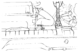
Position a vehicle on a level surface.

2.

Turn off the engine.

note

In the case of a vehicle that has not been used for a prolonged period, run the engine for several minutes.

Turn off the engine and wait for 5 minutes at least, then check the oil level.

3.

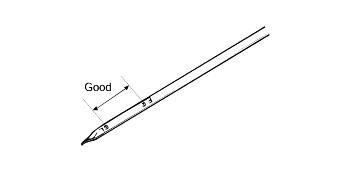
Check that the engine oil level is within the level range indicated on the oil dipstick. If the oil level is found to have fallen to the lowerlimit (the "L" mark), refill to the "F" mark.

note

When refilling, use the proper grade of engine oil.

4.

Check that the oil is not dirty or mixed with coolant or gasoline, and that it has the proper viscosity.

SELECTION OF ENGINE OIL

Recommended API classification: SH OR ABOVE SE OR ABOVE [For EC.]

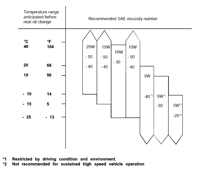
Recommended SAE viscosity grades:

note
1.

Satisfy the requirements of the API classification.

2.

Have the proper SAE grade number for expected ambient temperature range.

REPLACEMENT OIL FILTER
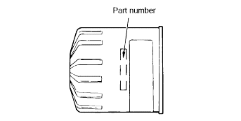
Filter selection
Procedure for Replacing Oil Filter
1.

Use a filter wrench to remove the oil filter.

2.

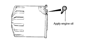
Before installing a new oil filter on the engine, apply clean engine oil to the surface of the rubber gasket.

3.

Tighten the oil filter of the specified torque.

Tightening torque

Oil filter : 17 - 25 Nm (170 - 250 kg.cm, 12 - 18 lb.ft)

4.

Start and run the engine and check engine oil leaks.

5.

After stopping the engine, check the oil level and add oil as necessary.

CHECKING COOLANT LEAK CHECK
1.

Loosen the radiator cap.

2.

Confirm that the coolant level is up to the filler neck.

3.

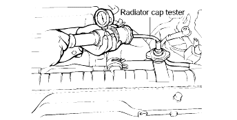
Install a radiator cap tester to the radiator filler neck and apply 150 KPa (21psi, 1.53 kg/cm²) pressure. Hold for two minutes, then checkfor leakage from the radiator, hoses or connections.

caution
1.

Radiator coolant may be extremely hot. Do not open the system while hot, or scalding engine coolant could gush out, causing personal injury. Allowthe vehicle to cool before servicing this system.

2.

When the tester is removed, be careful not to spill any coolant from it.

3.

Be sure to clean away completely any coolant from the area.

4.

Be careful, when installing and removing the tester and when testing, not to deform the filler neck of the radiator.

4.

If there is leakage, repair or replace with the apropriate part.

RADIATOR CAP PRESSURE TEST
1.

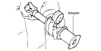
Use an adapter to attach the cap to the tester.

2.

Increase the pressure until the indicator of the gauge stops moving.

Main valve opening pressure :

107.9 ± 14.7 kPa (1.1 ± 0.15 kg/cm² , 15.64 ± 2.13 psi)

Main valve closing pressure :

83.4 kPa (0.85 kg/cm², 12.1 psi)

3.

Check that the pressure level is maintained at or above the limit.

4.

Replace the radiator cap if the reading does not remain at or above the limit.

note

Be sure that the cap is clean before testing, since rust or other foreign material on the cap seal will cause an incorrect reading.

SPECIFIC GRAVITY TEST
1.

1100Measure the specific gravity of the coolant with a hydrometer.

2.

Measure the coolant temperature and calculate the concentration from the relation between the specific gravity and temperature. Use the followingtable for reference.

RELATION BETWEEN COOLANT CONCENTRATION AND SPECIFIC GRAVITY

Coolant temperature °C (°F) and specific gravity

Freezing temperature °C (°F)

Safe operating temperature °C (°F)

Coolant concentration (Specific volume)

10 (50)

20 (68)

30 (86)

40 (104)

50 (122)

1.054

1.050

1.046

1.042

1.036

-16 (3.2)

-11 (12.2)

30%

1.063

1.058

1.054

1.049

1.044

-20 (-4)

-15(5)

35%

1.071

1.067

1.062

1.057

1.052

-25 (-13)

-20 (-4)

40%

1.079

1.074

1.069

1.064

1.058

-30 (-22)

-25 (-13)

45%

1.087

1.082

1.076

1.070

1.064

-36 (-32.8)

-31 (-23.8)

50%

1.095

1.090

1.084

1.077

1.070

-42 (-44)

-37 (-35)

55%

1.103

1.098

1.092

1.084

1.076

-50 (-58)

-45 (-49)

60%

caution

If the concentration of the coolant is below 30%, its anti-corrosion property will be adversely affected.

If the concentration is above 60%, the engine cooling property will decrease, affecting the engine adversely. For these reasons, be sure to maintainthe concentration level within the specified range.

Do not mix types of anti - freeze.

RECOMMENDED COOLANT

Antifreeze

Mixture ratio of antifreeze in coolant

ETHYLENE GLYCOL BASE FOR ALUMINUM

50% [Except tropical areas]

40% [Tropical areas]

CHECKING COMPRESSION PRESSURE
1.

Before checking the engine compression, check the engine oil level. Also check that the starter motor and battery are all in normal operatingcondition.

2.

Start the engine and wait until the engine coolant temperature reaches 80-95°C (176~205°F).

3.

Stop the engine and disconnect the spark plug cables.

4.

Remove the spark plugs.

5.

Crank the engine to remove any foreign material in the cylinders.

6.

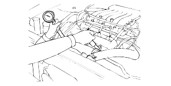
Insert the compression gauge into the spark plug hole.

7.

Depress the accelerator pedal to open the throttle fully.

8.

Crank the engine and read the gauge.

Standard value : 1,200kpa(12.2 kg/cm² , 170psi)

Limit : 1,050kpa(10.7kg/cm² , 149psi)

9.

Repeat steps 6 to 8 for all cylinders, making sure that the pressure difference for each of the cylinders is within the specified limit.

Limit :

Max. 100kpa (1.0 kg/cm², 14psi) between cylinders

10.

If a cylinder's compression or pressure differential is outside the specification, add a small amount of oil through the spark plug hole,and repeat steps 6 to 9.

(1)

If the addition of oil causes the compression to rise, it is possible that the piston ring is worn.

(2)

If the compression remains the same, valve seizure, poor valve seating or a compression leak in the cylinder head gasket are all possible causes.

Tightening torque

Spark plug : 20-30 Nm (200-300 kg.cm, 14-22 lb.ft)

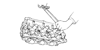
TIGHTENING CYLINDER HEAD BOLTS
1.

First loosen slightly and then tighten to the specified torque.

Tightening torque

Cylinder head bolts cold [Engine temperature approximately 20°C (68°F)] :

105 - 115 Nm (1050 - 1150 kg.cm, 75 - 82 lb ft.)

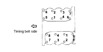
2.

Be sure to follow the specific torque sequence as shown in the illustration.

note

Run the engine to normal operating temperature and let it cool, then re-torque the bolts to specifications.

ADJUSTING VALVE CLEARANCE
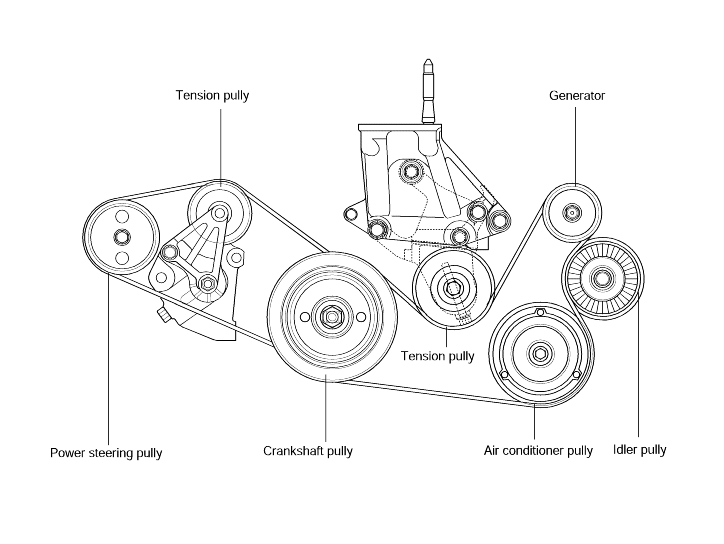
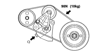
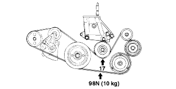
ADJUSTING DRIVE BELT AND TENSIONER
1.

Hang the belt on the pulley of the tensioner and install the tensioner.

(If the tensioner is already installed, loosen its mounting bolts to allow belt installation.)

Tightening torque

Tensioner assembly bolt :

45 - 50 Nm (450 - 500 kg.cm, 33 - 36 lb.ft)

2.

Install power steering belt.

3.

Install drive belt.

4.

Adjust the power steering belt tension to specification by turing the adjusting bolt (Q) clockwise or counterclockwise

5.

Adjust the drive belt tension to specification by turing the adjusting bolt (Q) clockwise or counterclockwise.

6.

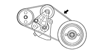
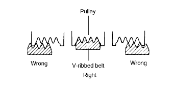
When installing the belt on the pulley, make sure it is centered on the pulley.

CHANGE ENGINE OIL
1.

Run the engine until it reaches normal operating temperature.

2.

Turn off the engine.

3.

Remove the oil filler cap and oil filter and then drain plug.

Drain the engine oil.

4.

Tighten the drain plug to the specified torque.

Tightening torque

Oil pan drain plug :

35 - 45 Nm (350 - 450 kg.cm, 25 - 33 lb.ft)

note

Whenever tightening the oil drain plug, use a new drain plug gasket.

5.

Fill the new engine oil through the oil filler cap.

Drain and Refill

Oil quantity : 4.3 lit (4.5 U.S. qts., 3.8 lmp. qts.)

note

Do not over fill. This will cause oil aeration and loss of oil pressure.

6.

Install the oil filler cap.

7.

Start and run the engine.

8.

Turn off the engine and then check the oil level. Add oil if necessary.

Яндекс.Метрика