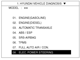
Select a model and ELECTRIC POWER STEERING.
After or before servicing the EPS system, perform the troubleshooting and test procedure as follows. Compare the system condition with normal condition in the table below and if abnormal symptom is detected, perform necessary remedy and inspection.
Test condition | Normal condition: Motor must not supply steering assist. | ||
Symptom | Possible cause | Remedy | |
IG Off | Motor supplies steering assist. | ASP is not calibrated. | Perform the ASP calibration using a scan tool. |
IG power supplies | Inspect the IG power supply line. | ||
Test condition | Normal condition: Motor must not supply steering assist, Warning lamp is illuminated. | ||
Symptom | Possible cause | Remedy | |
IG On/Engine Off | Motor supplies steering assist. | ASP is not calibrated. | Perform the ASP calibration using a scan tool. |
EMS CAN signal is not received. | Inspect the CAN line. | ||
Warning lamp is not illuminated. | Cluster fault | Inspect the cluster and cluster harness | |
Test condition | Normal condition: Motor supplies steering assist, Warning lamp is not illuminated. | ||
Symptom | Possible cause | Remedy | |
IG On/Engine On | Warning lamp is illuminated and Motor dose not supply steering assist. | EPS (Hot at all times) and IG power supply fault | Inspect the connector and harness for EPS (Hot at all times) and IG power supply line. |
DTC is detected by system. | Perform the self test using a scan tool and repair or replace. | ||
Warning lamp is illuminated and Motor supplies steering assist. | ASP is not calibrated. | Perform the ASP calibration using a scan tool. | |
CAN communication between EPS and cluster is fault. | Inspect the CAN line. | ||
ASP: Absolute Steering Position
CAN: Controller Area Network
EMS: Engine Management System
The following symptoms may be occurred during normal vehicle operation and if there is no EPS warning light illumination, it is not malfunction of EPS system.
After turning the ignition switch on, the steering wheel becomes heavier while it performs EPS system diagnostics, for about 2 seconds, then it becomes normal steering condition.
After turning the ignition switch on or off, EPS relay noise may occur but it is normal.
When it is steered, while the vehicle is stopped or in low driving speed, motor noise may occur but it is normal operating one.
Check if the battery is fully charged before ASP calibration or EPS type recognition.
Be careful not to disconnect any cables connected to the vehicle or scan tool during ASP calibration or EPS type recognition.
When the ASP calibration or EPS type recognition is completed, turn the ignition switch off and wait for several seconds, then start the engine to confirm normal operation if the vehicle.
Attach the CAN interface module to the Hi-Scan Pro main body and securely tighten the two bolts.
Install the CAN interface module to the Data Link Cable and securely tighten the two bolts.
Plug DLC cable from a scan tool into the vehicle's data link connector located under the instrument panel on the driver's side.
Turn the ignition switch ON position.
Turn the steering wheel so that the front wheel can face straight ahead.
Select a model and ELECTRIC POWER STEERING.

Select the ASP CALIBRATION and press ENTER.
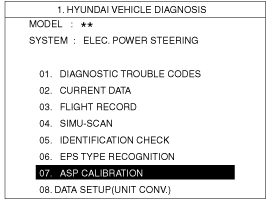
Check the massage on the screen and press ENTER'.
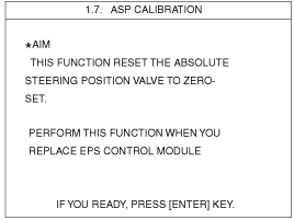
Confirm the vehicle condition (IG On) and then turn the steering wheel until massage changes to the next screen.
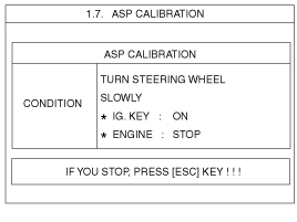
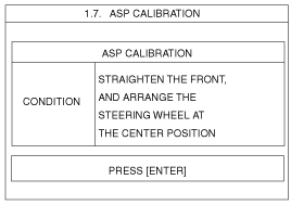
When the massage is displayed on the screen as follows, turn the steering wheel so that the front wheel can face straight ahead and then press ENTER.
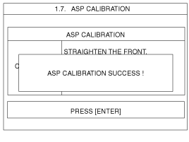
When the calibration is completed, the massage will be displayed on the screen as follows.
Plug DLC cable from a scan tool into the vehicle's data link connector located under the instrument panel on the driver's side.
Turn the ignition switch ON position.
Select a model and ELECTRIC POWER STEERING.

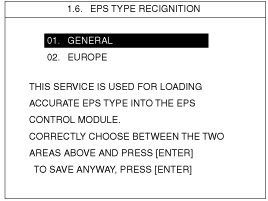
Select the EPS type recognition and press ENTER.

Select the affected area and press ENTER.
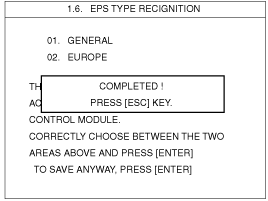
When the EPS type recognition is completed, the massage will be displayed on the screen as follows.
When DTC for parts in EPS unit assembly is detected by the system, clear the DTC and then inspect problem for detected DTC. Next, perform the self test using a scan tool and if the same DTC detected over again, do not repair the parts but replace the steering column & EPS unit assembly. After replacing the steering column & EPS unit assembly, perform ASP (Absolute Steering Position) calibration and EPS type recognition procedure using a scan tool. (Refer to ASP calibration and EPS type recognition)
DTC | FAILURE TYPE | INPECTION PROCEDURE |
C1101 | Battery voltage-high | 1. Measure resistance between the EPS ground terminal and chassis ground. Specification: Approx. 0Ω 2. Measure voltage between the EPS power supply terminal (Hot at all times) and chassis ground. Specification: 9 ~ 17V 3. Check the connectors and harness. 4. Inspect the charging system. |
C1102 | Battery voltage-low | Refer to C1101. |
C1103 | IG1 Voltage fail | 1. Measure between the EPS IG power supply terminal and chassis ground. Specification: Battery voltage 2. Check the connectors and harness. |
C1259 | SAS - Electrical malfunction | 1. Clear the DTC and IG Off and then operate the EPS system again. 2. Perform the self test using a scan tool and if same DTC is detected over again, replace the steering column & EPS unit assembly. |
C1261 | ASP is not calibrated | 1. Perform the steering angle sensor calibration using a scan tool. 2. Clear the DTC and IG Off and then operate the EPS system again. 3. Perform the self test using a scan tool and if same DTC is detected over again, replace the steering column & EPS unit assembly. |
C1290 | Torque sensor main signal fail | 1. Clear the DTC and IG Off and then operate the EPS system again. 2. Perform the self test using a scan tool and if same DTC is detected over again, replace the steering column & EPS unit assembly. |
C1603 | Derating (Thermal protection) | 1. Monitor the motor temperature on the scan tool. 2. Wait until the temperature drops below 80°C. 3. Clear the DTC and IG Off and then operate the EPS system again. |
C1604 | ECU hardware error | 1. Clear the DTC and IG Off and then operate the EPS system again. 2. Perform the self test using a scan tool and if same DTC is detected over again, replace the steering column & EPS unit assembly. |
C1611 | CAN time-out EMS | 1. Inspect the EMS and EPS CAN line. 2. Perform the self test using a scan tool and if same DTC is detected over again, replace the steering column & EPS unit assembly. |
C1616 | CAN bus off | 1. Measure resistance between the CAN High and CAN Low. Specification: Approx. 60Ω 2. If measured value is not within the specification, inspect the CAN line. 3. Perform the self test using a scan tool and if same DTC is detected over again, replace the steering column & EPS unit assembly. |
C1617 | EMS invalid engine speed | 1. Inspect the EMS and EPS CAN ine. 2. Clear the DTC and IG Off and then operate the EPS system again. 3. Perform the self test using a scan tool and if same DTC is detected over again, replace the steering column & EPS unit assembly. |
C1700 | Byte coding error | 1. Clear the DTC and IG Off and then operate the EPS system again. 2. Perform the self test using a scan tool and if same DTC is detected over again, replace the steering column & EPS unit assembly. |
C1702 | Variant coding error | 1. Perform the EPS type recognition procedure using a scan tool. 2. Clear the DTC and IG Off and then operate the EPS system again. 3. Perform the self test using a scan tool and if same DTC is detected over again, replace the steering column & EPS unit assembly. |
C1704 | ECU fail-safe relay fail | 1. Clear the DTC and IG Off and then operate the EPS system again. 2. Perform the self test using a scan tool and if same DTC is detected over again, replace the steering column & EPS unit assembly. |
C1705 | ECU pre-charge circuit fail | 1. Clear the DTC and IG Off and then operate the EPS system again. 2. Perform the self test using a scan tool and if same DTC is detected over again, replace the steering column & EPS unit assembly. |
C2101 | Motor relay circuit fail | 1. Clear the DTC and IG Off and then operate the EPS system again. 2. Perform the self test using a scan tool and if same DTC is detected over again, replace the steering column & EPS unit assembly. |
C2400 | Motor fail | 1. Clear the DTC and IG Off and then operate the EPS system again. 2. Perform the self test using a scan tool and if same DTC is detected over again, replace the steering column & EPS unit assembly. |
C2401 | Motor circuit fail | 1. Clear the DTC and IG Off and then operate the EPS system again. 2. Perform the self test using a scan tool and if same DTC is detected over again, replace the steering column & EPS unit assembly. |
C2412 | Motor short or open | 1. Clear the DTC and IG Off and then operate the EPS system again. 2. Perform the self test using a scan tool and if same DTC is detected over again, replace the steering column & EPS unit assembly. |
C2413 | Motor current (Over) | 1. Clear the DTC and IG Off and then operate the EPS system again. 2. Perform the self test using a scan tool and if same DTC is detected over again, replace the steering column & EPS unit assembly. |