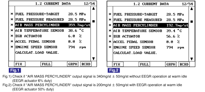
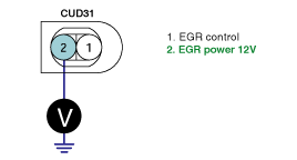
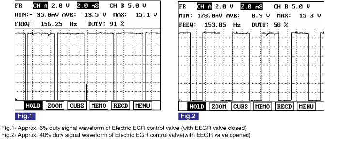
COMPONENT LOCATION
GENERAL DESCRIPTION

Receiving ECM signal, linear solenoid type electronic EGR actuator operates Electric EGR control valve directly.ECM performs EGR system feed back control with the information of measured mass air flow (The role of MAFS in diesel engine is different from gasoline engine. Fuel injection quantity is decided by MAFS signal in gasoline engine.)When EGR gas(contains no oxygen) flowing into combustion chamber increases, the air passing through MAFS(contains oxygen) decreases. Thus, with the output signal change of MAFS accompanied by Electric EGR control valve actuation, ECM determine the amount of recirculated EGR gas quantity.

note

NOx is produced from the reaction of nitrogen and oxygen. Controlling EGR gas(contains no oxyger) which is recirculated to combustion chamber, if least intake air required for complete combustion flows into combustion chamber, NOx decreases because there is no supplementary oxygen to react with nitrogen.

DTC DESCRIPTION

P0490 is set when excessive current is detected in Electric EGR control valve circuit for more than 0.5 sec.. This code is due to short to battery in Electric EGR control valve control circuit or internal short in Electric EGR control valve component.

DTC DETECTING CONDITION

Item

Detecting Condition

Possible Cause

DTC Strategy

Signal monitoring

Electric EGR control valve circuit

Electric EGR control valve component

Enable Conditions

Engine run

ThresholdValue

Short to battery

DiagnosticTime

500ms

Fail Safe

Fuel Cut

NO

EGR Off

YES

Fuel Limit

NO

MIL

NO

SIGNAL WAVEFORM AND DATA
note

The output of approx. 6% duty is mainly for the diagnosis of Electric EGR control valae circuit than actuating EEGR.

SPECIFICATION

Electric EGR control valve component resistance

Electric EGR control valve operating Hz

Electric EGR control valve operating duty

14.7 ~ 16.1Ω (20℃)

142Hz

5%(closed)~39%(opened)

SCHEMATIC DIAGRAM
MONITOR SCANTOOL DATA
1.

Connect Scantool to Data Link Connector (DLC).

2.

Warm engine up to normal operating temperature.

3.

Turn "OFF" electrical devices and A/C.

4.

Monitor "AIR MASS PERCYLINDER" parameter on the Scantool.

Specification : When Electric EGR control valve does not operate 6% duty) at idle : 340mg/st ± 50 mg/st

When Electric EGR control valve operates(Approx. 50% duty) at idle : 200ms/st ± 50 mg/st

※ Electric EGR control valve operates as decelerating after rapid acceleration when idle EEGR does not operate, Electric EGR control valve operating duty decreases as time goes by. This controlling process lasts for about 1 min. and EElectric EGR control valve turns "OFF" (duty 6% ) after 1 min..

TERMINAL AND CONNECTOR INSPECTION
1.

Electrical systems consist of a lot of harness and connectors, poor connection of terminals can cause various problems and damge of component.

2.

Perform checking procedure as follows.

(1)

Check damage of harness and terminals : Check terminals for contact resistance, corrosion and deformation.

(2)

Check connecting condition of ECM and component connector : Check terminal seperation, damage of locking device and connecting condition between terminal and wiring.

note

Disconnect the pin which requires checking at male connector and insert it to the terminal at female connector or checking connecting condition. ( after checking, reconnect the pin at correct position. )

3.

Is the problem found?

▶ Repair the trouble causing part and go to "Verification of Vehicle Repair".

▶ Go to "Power Circuit Inspection".

POWER CIRCUIT INSPECTION
1.

Check power circuit voltage

(1)

IG KEY "OFF", ENGINE "OFF".

(2)

Disconnect Electric EGR control valve connector

(3)

IG KEY "ON"

(4)

Measure the voltage of terminal 2 of Electric EGR control valve connector

Specification : 11.5V~13.0V

(5)

Is the measured voltage within the specification?

▶ Go to "Control Circuit Inspection".

▶ Repair E/R JUNCTION BOX 15A INJ fuse and related circuit and go to "Verification of Vehicle Repair".

CONTROL CIRCUIT INSPECTION
1.

Check control circuit monitoring voltage

(1)

IG KEY "OFF", ENGINE "OFF".

(2)

Disconnect Electric EGR control valve connector.

(3)

IG KEY "ON".

(4)

Measure the voltage of terminal 1 of Electric EGR control valve connector.

Specification : 3.2V~3.7V

(5)

Is the measured voltage within the specification?

▶ Go to "Component Inspection".

▶ When voltage is not detected : Go to "2. Check open in control circuit" as follows.

▶ When high voltage is detected : Repair short to battery and go to "Verification of Vehicle Repair".

2.

Check open in control circuit

(1)

IG KEY "OFF", ENGINE "OFF".

(2)

Disconnect Electric EGR control valve connector and ECM connector.

(3)

Check continuity between Electric EGR control valve terminal 1 and ECM connector(CUD-A) terminal 59.

specification : Continuity ( below 1.0Ω )

(4)

Is the measured resistance within the specification?

▶ Repair short to ground and go to "Verification of Vehicle Repair".

▶ Repair open in control circuit and go to "Verification of Vehicle Repair".

COMPONENT INSPECTION
1.

Check Electric EGR control valae component resistance

(1)

IG KEY "OFF", ENGINE "OFF".

(2)

Disconnect Electric EGR control valve.

(3)

Measure the resistance between EGR actuator component terminal 1 and 2.

Specification : 14.7 ~ 16.1Ω (20℃)

(4)

Is Electric EGR control valve component resistance within the specification?

▶ Go to "Verification of Vehicle Repair".

▶ Replace Electric EGR control valae and go to "Verification of Vehicle Repair".

VERIFICATION OF VEHICLE REPAIR

After a repair, it is essential to verify that the fault is corrected.

1.

After connecting Scantool select "DIAGNOSTIC TROUBLE CODES(DTCs)" mode.

2.

Clear recorded DTC using Scantool.

3.

Drive the vehicle within DTC "Enable conditions" in "General information".

4.

After selecting "DIAGNOSTIC TROUBLE CODES(DTCs)" mode and check if DTC is recorded again.

5.

Are any DTCs recorded ?

▶ Go to the DTC guide of recorded NO. in Scantool.

▶ System operates within specification.

Яндекс.Метрика