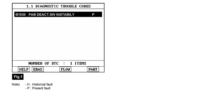
Using a scantool, clear the DTC.

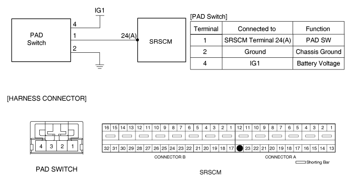
PAD Switch(Passenger airbag deactivation Switch) is the device which prevents Passenger airbag from being deployed when the passenger seat is unoccupied as driver turning OFF PAD Switch. When PAD Switch turned OFF, " PASSENGER SRS OFF" lamp on cluster turns ON.
The above DTC is recorded when PAD switch signal inputted to SRSCM changes for a while from ON to OFF and vise versa.
Item | Detecting Condition | Possible cause | |
DTC Strategy | ● Check current | ● Faulty PAD Switch. ● Faulty SRSCM. | |
Enable Conditions | ● Ignition "ON" | ||
Threshold value | ● Unstable input within 20 samples | ||
Diagnostic Time | Qualification | ● More than 1 sec | |
De-Qualification | ● N/A | ||
Test Condition | Current |
Ignition ON | ● PAB Enabled : 2.96 mA ≤ Current ≤ 5.01 mA ● PAB Disabled : 7.28 mA ≤ Current ≤ 12.73 mA |

Ignition "OFF", connect scantool.
Ignition "ON"& Engine "OFF", select "Diagnostic Trouble Codes(DTC)" mode.
Monitor diagnostic trouble code and present of trouble code.
Using a scantool, clear the DTC.

Is DTC present problem ?

▶ Go to "W/Harness Inspection" procedure.

▶ Do not change the Passenger airbag deactivation switch, Passenger airbag deactivation switch is OK at this moment. Fault is intermittent and caused either by poor contact in connectors or wiring harness, or it has been repaired and SRSCM memory is not cleared yet. Thoroughly check all connectors (and connections) for looseness, bending, corrosion, contamination, deterioration, and/or damage.
▶ Repair or replace as necessary and then go to "Verification of Vehicle Repair" procedure.
Many malfunctions in the electrical system are caused by poor harness and terminals.
Faults can also be caused by interference from other electrical systems, and mechanical or chemical damage.
Thoroughly check connectors for looseness, poor connection, bending, corrosion, contamination, deterioration, or damage.
Has a problem been found?

▶ Repair as necessary and then go to "Verification of Vehicle Repair" procedure.

▶ Go to "Control Circuit Open Inspection" procedure.
Ignition "OFF".
Disconnect the battery (+) & (-) terminal cable from the battery and wait at least one minutes.
Disconnect PAB SWITCH connector and SRSCM main harness connector.
Measure resistance between terminal "1" of the PAB SWITCH harness connector and chassis ground.
pecification : ∞

Is the measured resistance within specifications?

▶ After checking connecting condition and short to ground from PAB SWITCH harness to SRSCM harness, repair or replace it if needed and go to "Verification and Vehicle Repair".
▶ Go to "Component Inspection".

▶ After replacing harness and go to "Verification and Vehicle Repair".
Ignition "OFF".
Substitute with a known-good PAB SWITCH.
Using a scantool, clear the DTCs.
Is DTC "B1530" present ?

▶ Poor contact at the SRS main harness connector; check the connector.
▶ If the connector is OK,substitute a known-good SRSCM, and check for proper operation.
If the problem is corrected, replace SRSCM and then go to "Verification of Vehicle Repair" procedure.
▶ If the problem is still present, substitute the SRS main harness and check for proper operation.
If the problem is corrected, replace SRS main harness and then go to "Verification of Vehicle Repair" procedure.

▶ Substitute a known-good PAB SWITCH, and check for proper operation.
If the problem is corrected, replace satellite driver sensor and then go to "Verification of Vehicle Repair" procedure.
Refer to the DESCRIPTION in this TROUBLESHOOTING section.