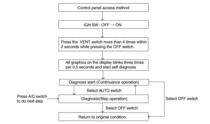
Self-diagnosis process
The F.A.T.C. module self test feature will detect electrical malfunction and provide error codes for system components with suspected failures.

DTC data can be retrieved from the control panel directly.
Self-diagnosis process
The F.A.T.C. module self test feature will detect electrical malfunction and provide error codes for system components with suspected failures.

DTC data can be retrieved from the control panel directly.
How to read self-diagnostic code
After the display panel flickers three times every 0.5 second, the corresponding fault code flickers on the setup temperature display panel every 0.5 second and will show two figures. Codes are displayed in numerical format.
Fault code | Fail description |
Control unit | |
00 | Normal |
11 | In-car temperature sensor open (High) |
12 | In-car temperature sensor short (Low) |
13 | Ambient temperature sensor open (High) |
14 | Ambient temperature sensor short (Low) |
15 | Water temperature sensor open (High) |
16 | Water temperature sensor short (Low) |
17 | Evaporator temperature sensor open (High) |
18 | Evaporator temperature sensor short (Low) |
19 | Temp door potentiometer open/short |
20 | Temp door motor |
21 | Vent mode door potentiometer open/short |
22 | Vent mode door control motor |
25 | Intake door potentiometer open/short |
26 | Intake door potentiometer motor |
27 | AQS sensor open |
28 | AQS sensor short |
31 | AQS sensor fault |
34 | Floor mode door potentiometer open/short |
35 | Floor mode door potentiometer motor |
36 | Def mode door potentiometer open/short |
37 | Def mode door potentiometor motor |
Fault code display
Continuance operation : DTC code is one

Continuance operation : DTC code is more two

Step operation
Nomal or one fault code is same a continuance operation.
DTC code is more two.

If fault codes are displayed during the check, Inspect malfunction causes by referring to fault codes.
Fail safe
In-car temperature sensor: Control with the value of 25°C (77°F)
Ambient temperature sensor: Control with the value of 20°C (67°F)
Evaporator temperature sensor: Control with the value of -2°C (28.4°F)
Water temperature sensor : control with the value of -2°C (28.4°F)
Humidity sensor: Doesn't control.
Photo sensor: None correction
Temperature control actuator (Air mix potentiometer):
If temperature set 15°C-22°C, fix at maximum cooling position.
If temperature set 23°C-30°C, fix at maximum heating position.
Mode control actuator (Direction potentiometer):
INDICATOR OFF : Door close position
INDICATOR ON : Door open position
Intake control actuator
Fix fresh position, while selecting fresh mode.
Fix recirculation position, while selecting recirculation mode.
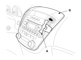
Disconnect the negative (-) battery terminal.
Put the SST (A) into the space betwen the center facia (A).

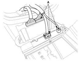
Disconnect the connectors (A) from the center facia.

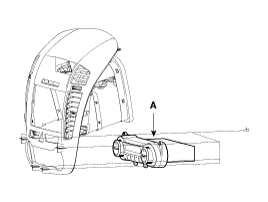
Remove the Heater & A/C controller (A) after loosening 4 screws.

Installation is the reverse order of removal.