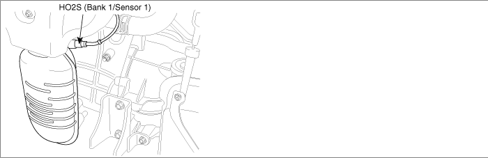
The HO2S(Heated Oxygen Sensor) is used to supply the ECM with information regarding the composition of the air/fuel mixture. The HO2S is positioned in the exhaust pipe ahead of the TWC. To measure the oxygen content, the HO2S requires a supply of ambient air as a reference. Since this is supplied through the wiring, the lead must not be clamped or damaged in any other way. The HO2S produces a voltage that varies between 0.1V and 0.9V under normal operating conditions. The Engine Control Module (ECM) monitors this voltage and determines if the exhaust gas is lean or rich. If the voltage input at the ECM is under approx. 0.45V the exhaust is lean, and if the voltage input is over approx. 0.45V the exhaust is rich. The ECM constantly monitors the HO2S signal during closed loop operation and compensates for a rich or lean condition by decreasing or increasing injector pulse width as necessary.
DTC DESCRIPTION
The ECM monitors the HO2S(B1/S1) transition frequency for predetermined time. During the monitoring period, the ECM calculates transition times that the front HO2S switches from rich to lean and from lean to rich. With this information, an average frequency for all switches can be determined. The ECM sets DTC P0133 when the average frequency is too slow.
DTC DETECTING CONDITION
Item
Detecting Condition
Possible Cause
DTC Strategy
●
HO2S signal ampliture check
●
Leak in intake or exhaust system
●
Faulty fuel system.
●
Front and rear HO2S connections reversed.
●
Contact resistance in connectors
●
HO2S contamination
Enable Conditions
●
400℃ < Modeled catalyst temp. < 902℃
●
Lambda regulation active
●
Stable driving condition
●
Canister closed < 0.5
●
Canister purge closed
●
Engine speed(rpm) < 3400
●
Coolant temperature > 74℃
●
5 <Vehicle speed(km/h) < 180
●
No relevant failure
●
11V < Battery voltage
Threshold Value
●
Time ration between rich to lean or lean to rich exceeds threshold value
Diagnostic Time
●
50 lambda controller cycles
MIL On Condition
●
2 Driving Cycles
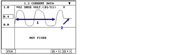
SIGNAL WAVEFORM AND DATA
Test Condition
Scan Tool Parameter
O2 SNSR VOL.-B1/S1
O2 SNSR VOL.-B1/S2
Normal Value when circuit is normal
Idle after warm up
Signal is switching from rich(above 0.45V) to lean(below 0.45V) a minimum of 3 times in 10 seconds.
above 0.7V
HO2S(B1S1) signal circuit open
Approx. 0.43~0.45V
-
HO2S(B1S2) signal circuit open
-
Approx. 0.43~0.45V
1.
Normal value with idle after warm up : Signal is switching from rich(above 0.45V) to lean(below 0.45V) a minimum of 3 times in 10 seconds.
2.
Scan tool display with open in signal circuit : Approx. 0.43~0.45V
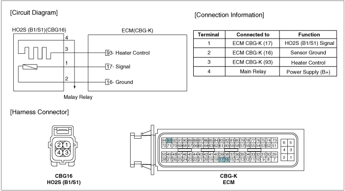
SCHEMATIC DIAGRAM
MONITOR DTC STATUS
1.
Connect scan tool and select "Diagnostic Trouble Codes(DTCs)" mode.
2.
Press F4(DTAL) to select DTC information from the DTCs menu.
3.
Confirm that "DTC Readiness Flag" indicates "Complete". If not, drive the vehicle within conditions noted in the freeze frame data or enable conditions.
4.
Read "DTC Status" parameter.
5.
Is parameter displayed "History(Not Present) fault"?
note
-
History (Not Present) fault : DTC occurred but has been cleared.
-
Present fault : DTC is occurring at present time.
▶ Fault is intermittent caused by poor contact in the sensor's and/or ECM's connector or was repaired and ECM memory was not cleared. Thoroughly check connectors for looseness, poor connection, bending, corrosion, contamination, deterioration, or damage. Repair or replace as necessary and then go to "Verification of Vehicle Repair" procedure.
▶ Go to next step as below.
AIR LEAKAGE INSPECTION
1.
Visually/physically inspect the following items:
A.
Vacuum hoses for splits, kinks and improper connections.
B.
Exhaust system between HO2S and Three way catalyst for air leakage
C.
EVAP system for leakage
D.
PCV hose for proper installation
2.
Was a problem found in any of the above areas?
▶ Repair as necessary and go to "Verification of Vehicle Repair" procedure
▶ Go to next step as below
VISUAL / PHYSICAL INSPECTION
1.
Visually/physically inspect the following items:
A.
Check for corrosion on terminals
B.
Check for terminal tension ( at the HO2S and at the ECM)
C.
Check for damaged wiring
D.
Check the HO2S ground circuit for a good connection
E.
Check front and rear HO2S for connections being reversed.
2.
Was a problem found in any of the above areas?
▶ Repair as necessary and go to "Verification of Vehicle Repair" procedure
▶ Go to next step as below
COMPONENT INSPECTION
1.
Visually/physically inspect the following conditions:
A.
Ensure that the HO2S is securely installed.
B.
Silicon contamination. This contamination will be indicated by a white powdery coating on the portion of the sensor exposed to the exhaust stream and this will result in a but false(high) voltage signal
C.
Fuel, engine coolant or oil contamination
D.
Use of improper sealant
E.
If contamination is evident on the HO2S, Fix the source of the sensor contamination before replacing the sensor to prevent future contamination. Go to "Verification of Vehicle Repair" procedure.
2.
Warm up the engine to normal operating temperature and let it idle.
3.
Connect Scantool and monitor the O2 SNSR VOL.-B1/S1 parameter on the Scantool data list.
Specification : Refer to "Signal Waveform & Data" in the "General Information" procedure. Verify signal is switching from rich(above 0.45V) to lean(below 0.45V) a minimum of 3 times in 10 seconds (voltage will vary between 0.1 and 0.9V) at idle.
4.
Is sensor switching properly?
▶ Check for poor connection between ECM and component: backed out terminal, improper mating, broken locks or poor terminal to wire connection. Repair as necessary and go to "Verification of Vehicle Repair" procedure
▶ Check HO2S for contamination, deterioration, or damage. Substitute with a known-good HO2S and check for proper operation. If the problem is corrected, replace HO2S and then go to "Verification of Vehicle Repair" procedure
VERIFICATION OF VEHICLE REPAIR
After a repair, it is essential to verify that the fault has been corrected.
1.
Connect scan tool and select "Diagnostic Trouble Codes(DTCs)" mode.
2.
Press F4(DTAL) and confirm that "DTC Readiness Flag" indicates "Complete". If not, drive the vehicle within conditions noted in the freeze frame data or enable conditions.
3.
Read "DTC Status" parameter.
4.
Is parameter displayed "History(Not Present) fault"?
▶ System performing to specification at this time. Clear the DTC