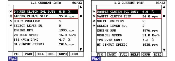
Monitor the "TORQUE CONVERTER(DAMPER) CLUTCH" parameter on the scantool.
Specification : TCC SLIP>5RPM


Fig 1) "P,N"
Fig 2) "R"
Fig 3) "1st" grar
Fig 4) "2nd" gear
Fig 5) "3rd" gear
Fig 6) "4th" gear
The TCM controls the locking and unlocking of the Torque Converter Clutch ( or Damper Clutch ), to the input shaft of the transmission, by appling hydraulic pressure. The main purpose of T/C clutch control is to save fuel by decreasing the hydraulic load inside the T/C. The TCM outputs duty pulses to control the Damper Clutch Control Solenoid Valve( DCCSV ) and hydraulic pressure is applied to the DC according to the DCC duty ratio value. When the duty ratio is high, high pressure is applied and the Damper Clutch is locked. The normal operating range of the Damper Clutch Control duty ratio value is from 30%(unlocked) to 85%(locked).
The TCM increases the duty ratio to engage the Damper Clutch by monitoring the slip rpms (difference vlaue beteween engine speed and turbine speed ). If a very small amount of slip rpm is maintained though the TCM applies 0% duty ratio value, then the TCM determines that the Torque Converter Clutch is stuck ON and sets this code.
Item | Detecting Condition | Possible Cause |
DTC Strategy | ● Stuck "ON" | ※ TORQUE CONVERTER(DAMPER) CLUTCH : TCC ● Faulty TCC or oil pressure system ● Faulty TCC solenoid valve ● Faulty bady control valve ● Faulty TCM(PCM) |
Enable Conditions | ● Throttle position >20% ● Output speed >1000rpm ● Engine speed >0rpm ● A/T range switch D,3 ● The time after the last shift was finished >3secs ● Duty of Damper clutch solenoid valve = 0% ● ATF temperature > -10℃ | |
Threshold Value | ● |Engine rpm - Input speed sensor rpm| ≤ 5 rpm | |
Diagnostic Time | ● More than 3 seconds | |
Fail Safe | ● Damper clutch abnormal system(If diagnosis code P0741 is output four times, TORQUE CONVERTER(DEMPER) CLUTCH is not controlled by PCM/TCM) |
Connect scantool to data link connector(DLC)
Engine "ON" .
Sellect "D RANGE" and drive vehicle.
Monitor the "TORQUE CONVERTER(DAMPER) CLUTCH" parameter on the scantool.
Specification : TCC SLIP>5RPM


Fig 1) "P,N"
Fig 2) "R"
Fig 3) "1st" grar
Fig 4) "2nd" gear
Fig 5) "3rd" gear
Fig 6) "4th" gear
Is TCC SLIP" within specifications ?
 | ▶ Fault is intermittent caused by poor contact in the sensor's and/or PCM/TCM's connector or was repaired and PCM/TCM memory was not cleared. Throughly check connectors for looseness, poor connection, bending, corrosion, contamination, deterioration or damage.Repair or replace as necessary and go to "Verification Vehicle Repair" procedure . |
 | ▶ Go to "Component Inspection" procedure. |
Connect scantool to data link connector(DLC)
Ignition "ON" & Engine "OFF".
Select A/T Solenoide valve Actuator test and Operate Actuator test.
Is Actuator Testing performed normally ?

 | ▶ Go to "CHECK OIL PRESSURE" as below. |
 | ▶ Repair or Replace as necessary and then go to "Verification Vehicle Repair" procedure. |
Connect Oil pressure guage to "DR" port.
Ignition "ON" & Engine "OFF".
After connecting Scantool and monitor the "TCC SOLENIOD VALVE DUTY" parameter on the Scantool data list.
Select 1st gear and accelerate Engine speed to 2500 rpm.
Measure oil pressure.
Is oil pressure value within specification?
Specification : Approx. Above 5.1~7.1kg/㎠
 | ▶ Repair TORQUE CONVERTER CLUTCH(REPLACE Torque Converter ) as necessary and Go to "Verification Vehicle Repair " procedure. |
 | ▶ Replace A/T ass'y (possible to BODY CONTROL VALVE faulty) as necessary and Go to "Verification Vehicle Repair " procedure. |
After a repair, it is essential to verify that the fault has been corrected.
Connect scan tool and select "Diagnostic Trouble Codes(DTCs)" mode.
Using a scantool, Clear DTC.
Operate the vehicle within DTC Enable conditions in General information.
Are any DTCs present ?
 | ▶ Go to the applicable troubleshooting procedure. |
 | ▶ System performing to specification at this time. |