4.
Monitor the "WHEEL SPD SNSOR-FL, FR, RL, RR" parameter on the Scantool.
Specification : Compare with other parameters related to wheel speed sensor. If it is the same as other parameters, it is in normal condition.
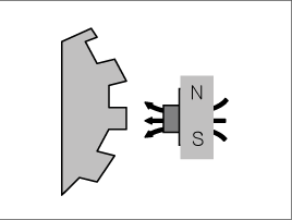
The wheel speed sensor is the essential component the ABS ECU uses to calculate vehicle speed and to determine whether wheel lock occurs. For example, rear wheel speed signal is used as a referecnce value, for vehicle speed, in front wheel drive vehicles, and if a difference between front and rear wheel speed occurs, then ABS control is performed. Wheel speed sensor is active hall-sensor type.
The ABS ECU monitors the wheel speed sensor signal continuously. This code is set when there is no wheel speed signals within 10 ms to 20 ms at a vehicle speed > 43.2 km/h or a deviation between sensors exceed the threshold or one or two wheels are at 2.75 km/h while the vehicle speed is at 12 km/h. Warning lamp is turned OFF unless additional faults are detected when the IG KEY is turned ON again, and wheel speed is more than 12 Km/h.
Item | Detecting Condition | Possible cause | ||
DTC Strategy | ● Signal monitoring | ● Improper installation of wheel speed sensor ● Abnormal Rotor and wheel bearing ● Faulty Wheel speed sensor (FL, FR, RL, RR) | ||
Case1 | Monitoring Period | ● Continuous (the conditions below are met and no under voltage is not detected) | ||
Enable Conditions | ● If one (or two) wheel are at 2.75km/h and the other wheels are above 12 km/h for longer than 1s. ● During driving, when the vehicle accelerates 18km/h after a particular wheel speed gets to 2.75km/h and stays there. At that time, If one (or two) wheel are at 2.75km/h. - This monitoring is performed at the vehicle is accelerated to 12km/h
● If one (or two) wheels are under 5km/h and the two fastest wheels have a velocity above 12km/h for more than 20s. - This monitoring is performed continuously. | |||
Case2 | Monitoring Period | ● Continuous ( If vehicle speed > 12 m/s(43.2 km/h)) - but this monitoring is disabled in the following event
| ||
Enable Conditions | ● No wheel speed signals within 10 ms to 20 ms at a vehicle speed > 12 m/s (43.2 km/h ). - If the dynamic sensor monitor responses, the failures will be stored into failure memory immediately after a waiting period of 60 ms. - If occurs low voltage active sensors during the waiting period of 60 ms no failure is stored in the EEPROM. | |||
Case3 - ABS Only | Monitoring Period | ● Continuous | ||
Enable Conditions | ● Vehicle < 100Km/h - Difference of two wheel speeds at FL to RL/FR to RR>1.7m/s (6km/h). - Difference of two wheel speeds at FL to FR/RL to RR>1.7m/s + 1.1m/s. - Difference of two wheel speeds at FL to RR/FR to RL>1.7m/s + 2.2m/s. ※ If at least one wheel is at 1.4m/s or lower, a wheel speed difference of adjoining wheels up to 3.3m/s(or 3.3m/s + 1.1m/s) is permitted. ● Vehicle > 100Km/h - Difference of two wheel speeds at FL to RL/FR to RR>(6%×Vref). - Difference of two wheel speeds at FL to FR/RL to RR>(6%×Vref + 1.1m/s). - Difference of two wheel speeds at FL to RR/FR to RL>(6%×Vref + 2.2m/s). ※ V_ref : Vehicle Reference Speed difference and additional conditions as shown below. 1. 18s - if fault threshold is exceeding > 1.7m/s resp.6% 2. 9s - if fault threshold is exceeding > 3.3m/s resp. 12% 3. If any wheel shows strong deceleration the fault detection filter time is not shorter than 18s. 4. If spinning wheel is detected the fault detection filter time is not shorter than 72s. ● Fault allocation If the exact fault location can be determined the wheel specific fault will be set. This is the case if at the time of detection the faulty wheel speed is at or below 1.4m/s. Otherwise a general WSS_Generic fauly (C1213) is set. ● Detection filter time - Response and detection filter time depend on the amount of the speed. | |||
Case4 - ESP Only | Monitoring Period | ● Main Monitoring - The main monitor needs additional information of the ESP-sensors and is active for a velocity > 20 km/h and no under voltage is detected. ● Backup Monitoring - Continuous | ||
Enable Conditions | ● Main Monitoring
● Backup Monitoring
| |||
Fail Safe | ● Sensor failure outside of the ABS control cycle
● Sensor failure inside the ABS control cycle
● ※ Control of the corresponding wheel is no longer possible. If a sensor fault occurs on a front wheel, pressure is increased; on a rear wheel, pressure is decreased. | |||
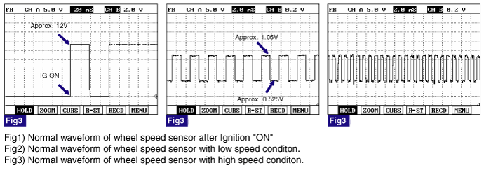
Sensor Type | Output Voltage | Air Gap | |
HIGH | LOW | ||
Active Type | 1.05V | 0.525V | 0.7mm |
Ignition "ON" & Engine "ON".
Connect scantool to Data Link Connector(DLC).
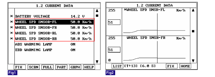
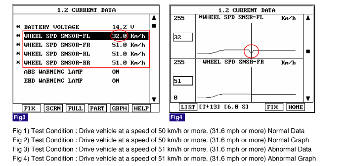
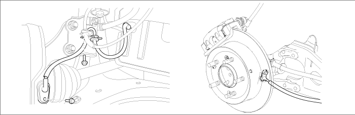
Start and drive vehicle in gear and maintain vehicle speed at or above 50 km/h(31.1 mph)
Monitor the "WHEEL SPD SNSOR-FL, FR, RL, RR" parameter on the Scantool.
Specification : Compare with other parameters related to wheel speed sensor. If it is the same as other parameters, it is in normal condition.
Is parameter displayed within specifications?

▶ Fault is intermittent caused by poor connection in wheel speed sensor harness (FL, FR, RL, RR) and/or HECU's connector or was repaired and HECU memory was not cleared. Thoroughly check connectors for looseness, poor connection, bending, corrosion, contamination, deterioration, or damage. Repair or replace as necessary and then go to "Verification of Vehicle Repair" procedure.

▶ Go to "Component Inspection" Procedure.
Lift the vehicle.
Ignition "ON" & Engine "OFF".
Turn the wheel by hand.
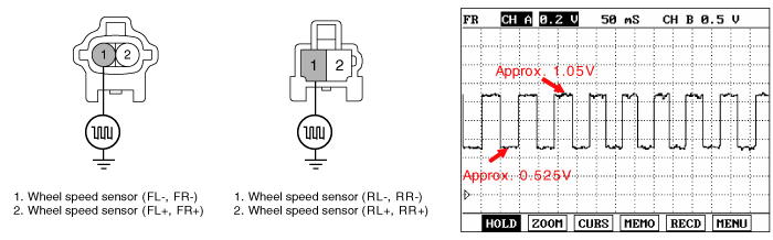
Measure waveform between terminal "FL, FR : 1, RL, RR : 1" of the wheel speed sensor harness connector and chassis ground.
Specification : High : 1.05 V , Low : 0.525 V
Is the measured waveform within specifications ?
▶ Fault is intermittent caused by poor connection in wheel speed sensor harness. Thoroughly check connectors for looseness, poor connection, bending, corrosion, contamination, deterioration, or damage. Repair or replace as necessary and then go to "Verification Of Vehicle Repair" procedure.
▶ If OK, Substitute with a known-good HECU and check for proper operation. If problem is corrected, replace HECU and then go to "Verification Of Vehicle Repair" procedure.
▶ Check for improper installation of wheel speed sensor. If NG, repair as necessary and then go to "Verification Of Vehicle Repair" procedure.
▶ Check for damage of rotor teeth or wheel bearing. If NG, repair as necessary and then go to "Verification Of Vehicle Repair" procedure.
▶ Substitute with a known-good Wheel speed sensor and check for proper operation. If problem is corrected, replace Wheel speed sensor and then go to "Verification Of Vehicle Repair" procedure.
After a repair, it is essential to verify that the fault has been corrected.
Connect scantool and select "Diagnostic Trouble Codes (DTCs)" mode
Using a scantool, Clear DTC.
Operate the vehicle within DTC Detecting Condition in General Information.(Start and drive vehicle in gear and maintain vehicle speed at or above 50 km/h (31.1 mph))
Are any DTCs present ?
▶ Go to the applicable troubleshooting procedure.
▶ System performing to specification at this time.
