Component Inspection
■ Check "INPUT SPEED SENSOR"
1.

Ignition "OFF"

2.

Disconnect the "INPUT SPEED SENSOR" connector

3.

Measure resistance between terminal "1","2" and "2","3" and "1","3" of the "INPUT SPEED SENSOR" connector .

Specification : Refer to " Reference data"

note
To view Flash content, you need to install the appropriate browser extension
4.

Is resistance within specifications?

[Reference data]

Data

Reference Data

Current

22 mA

Air Gab

Input sensor

1.3 mm

Output sensor

0.85 mm

Resistance

Input sensor

Above 4 ㏁

Output sensor

Above 4 ㏁

Voltage

High

4.8 ~ 5.2V

Low

Below 0.8V

▶ Go to "CHECK PCM/TCM " as below

▶ Replace "INPUT SPEED SENSOR" as necessary and Go to "Verification Vehicle Repair" procedure.

■ Check PCM/TCM
5.

Ignition "ON" & Engine "OFF".

6.

Connect "INPUT SPEED SENSOR" connector.

7.

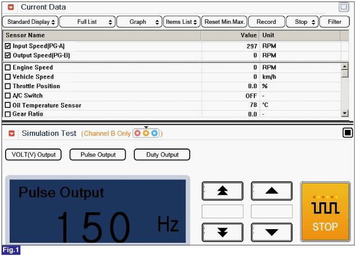
Install GDS and slect a SIMU-SCAN,

8.

Simulate frequency to INPUT SPEED SENSOR signal circuit.

Fig 1) INPUT 150Hz → 297rpm

Fig 2) INPUT 250Hz → 495rpm

※ The values are subject to change according to vehicle model or conditions

9.

Is "INPUT SPEED SENSOR" signal value changed according to simulation frequency?

▶ Thoroughly check connectors for looseness, poor connection, bending, corrosion, contamination, deterioration, or damage. Repair or replace as necessary and then go to "Verification of Vehicle Repair" procedure.

▶ Substitute with a known-good PCM/TCM and check for proper operation. If the problem is corrected, replace PCM/TCM as necessary and then go to "Verification of Vehicle Repair" procedure.

Яндекс.Метрика