
The value of the input shaft speed should be equal to the value of the output shaft speed, when multiplied by the 1st gear ratio, while the transaxle is engaged in the 1st gear. For example, if the output speed is 1000 rpm and the 1st gear ratio is 2.842, then the input speed is 2842 rpm.
This code is set if the value of input shaft speed is not equal to the value of the output shaft, when multiplied by the 1st gear ratio, while the transaxle is engaged in 1st gear. This malfunction is mainly caused by mechanical troubles such as control valve sticking or solenoid valve malfuctioning rather than an electrical issue.
Item | Detecting Condition | Possible Cause |
DTC Strategy |
•
1st gear incorrect ratio |
•
Faulty Input speed sensor
•
Faulty output speed sensor
•
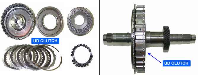
Faulty UD clutch or LR brake or Oneway clutch |
Enable Conditions |
•
Engine speed >400rpm
•
Output speed >200rpm
•
Lever position : D,3,2,L
•
Input speed >300rpm
•
A/T oil temp output ≥ -10℃
•
TRANSAXLE RANGE SWITCH is normaland after 2sec is passed from IG ON | |
Threshold Value |
•
ㅣInput speed/1st gear ratio - output speed|≥200rpm | |
Diagnostic Time |
•
More than 1sec | |
Fail Safe |
•
Locked into 3 rd gear.(If diagnosis code P0731 is output four times, the transaxle is locked into 3rd gear) |
Input shaft & Output shaft speed sensor
Type : Hall sensor
Current consumption : 22mA(MAX)
Sensor body and sensor connector have been unified as one
A : INPUT SPEED SENSOR
B : OUTPUT SPEED SENSOR