
W/O ISG
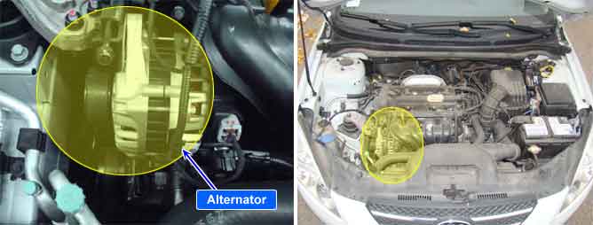
Alternator output and power demand of all electrical loads and systems must be matched to each other as ideally as possible so that the entire system is reliable and trouble-free in operation. The ECM monitors alternator output deviation from the signal of the FR terminal of the alternator when the engine is running.
ISG
ISG System has alternator in which there is a communication regulator in order to compensate current loss resulting from repetitive starting. The alternator is duty controlled as current control by ECM with the battery voltage, current, temperature information from battery sensor. The more electrical load, the higher duty output.
ISGISG System has alternator in which there is a communication regulator in order to compensate current loss resulting from repetitive starting. The alternator is duty controlled as current control by ECM with the battery voltage, current, temperature information from battery sensor. The more electrical load, the higher duty output.
ECM sets DTC P0626 if the ECM detects that the alternator's output duty signal is 0%.
Item | Detecting Condition | Possible Cause |
DTC Strategy |
•
Input signal check |
•
Open or Short to Power in harness
•
Faulty charging system |
Enable Conditions |
•
Battery voltage < 16V
•
Engine speed : 600 ~ 4000
•
Engine coolant temp. > 75℃ | |
Threshold Value |
•
Duty calculated by Alternator PWM signal = 0% | |
Diagnostic Time |
•
100sec. | |
MIL ON Condition |
•
DTC only |
Fig.1) Idle Status
Fig.2) Electrical Load (Head Lamp and Defrost are ON
Duty(+) from FR terminal is increased if electrical loads are ON (Head Lamp and Defrost are ON) ECM controls generation of alternator with duty from FR terminal when electrical Loads turn on