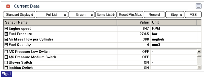
Monitor "ENGINE SPEED SENSOR" parameter on the GDS.
Specification : 800±50RPM at idle

Fig 1) Check "ENGINE SPEED SENSOR" parameter carefully after warming engine up, also check engine stall and rpm instability or engine shut down.

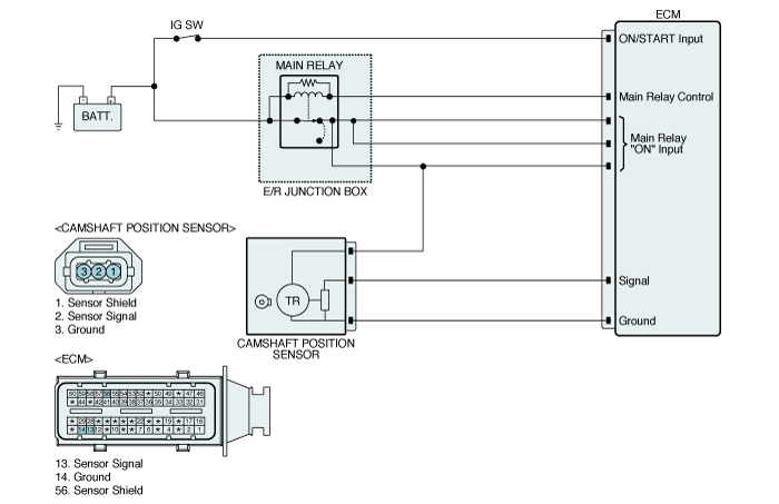
Crank Shaft Position Sensor(CKPS) is magnetic inductive type. Mounted on transaxle hausing, it senses tone wheel position of fly wheel.
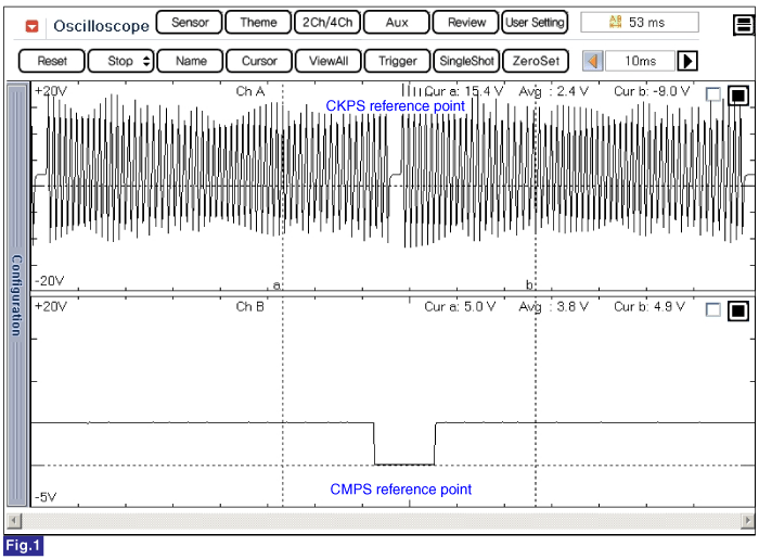
As tone wheel is devided with 58 teeth and 2 missing teeth (referrence point), 1 tooth corresponds to 6 degree.
CKPS which calculates RPM and crank angle is important to determine fuel injection quantity and injection timing with APS.
Crank shaft position is closely related to engine starting.
P0336 is set when 1). engine speed detected by CKPS is above 6000RPM, or 2). CKPS signal pulse is abnormal. For repair, check temporary poor connection in CKPS circuit, component failure or deformation of tone wheel.
Item | Detecting Condition | Possible Cause | ||
DTC Strategy | ● Signal monitoring | ● CKPS circuit ● CKPS component ● Abnormal deformation of Crank Shaft tone wheel | ||
Enable Conditions | ● Engine running | |||
Threshold Value | ● Engine speed sensed at CKPS above 6000RPM ● Abnormal crank signal pulse | |||
Diagnostic Time | ● Immediately | |||
Fail Safe | Fuel cut | YES | ||
EGR Off | NO | |||
Fuel Limit | NO | |||
Check Lamp | YES | |||
Sensor Type | Output Signal Characteristic | Air Gab | Low RPM Minimum Detecting Voltage | High RPM Minimum Detecting Voltage |
Magnetic inductive | A/C waveform | 1.8mm | 230mV | 2769 mV |


Fig.1) This shows waveform of Crank Shaft Position Sensor and Cam Shaft Position Sensor simulatneously. The middle area indicates reference points of Crank Shaft Position Sensor and Cam Shaft Position Sensor.
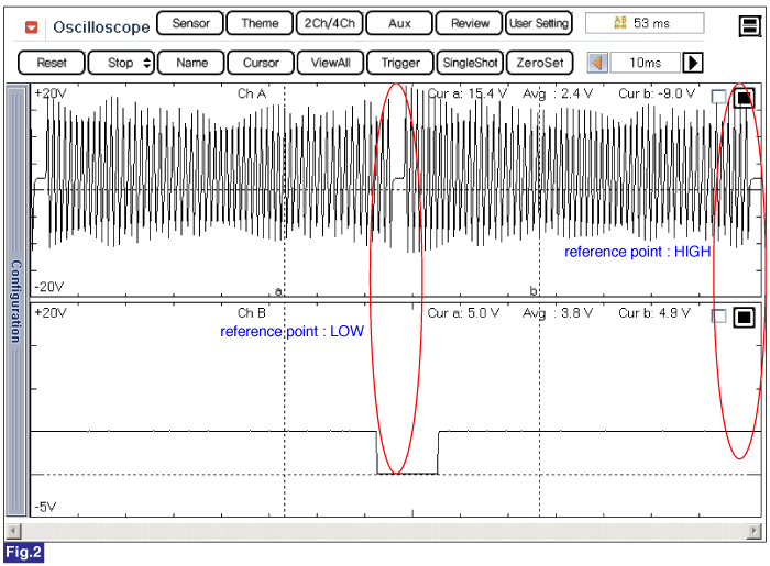
Fig.2) Crank Shaft Position Sensor and Cam Shaft Position Sensor signal are measured simultaneously. Cam Shaft Position Sensor signal is outputted once when Crank Shaft Position sensor signal is outputted twice. LOW and HIGH output of Cam Shaft Position sensor reference point is detected at Crank Shaft Position sensor reference point. ( Injection sequence is determined based on LOW and HIGH signal of Cam Shaft Position Sensor reference point as detecting cylinder position.)
※ Signal Analysis

1) The output voltage of CKPS signal varies according to rpm(the speed of tone wheel passing by sensor)
( low voltage is inducted for low speed and high voltage is inducted for high speed. )
2) CKPS should detect from low rpm at cranking to above 5000rpm. If minimum detecting voltage is set low for the ease of signal detection at low rpm, 1) the abnormal signal at high rpm from which high voltage generates or 2) electrical NOise through circuit can be recognized as Crank signal. Thus minimum detecting voltages at low rpm and high rpm are set differently.
3) ECM convert analog signal like the waveform illustrated above into digital signal with A/D converter.The voltage above minimum detecting voltage of crank signal and "-"voltage below 0.0V is meaningless at converting process. RPM is detected as Hz.(signal detecting period)
Connect GDS to Data Link Connector (DLC).
Warm engine up to normal operating temperature.
Turn "OFF" electrical devices and A/C.
Monitor "ENGINE SPEED SENSOR" parameter on the GDS.
Specification : 800±50RPM at idle

Fig 1) Check "ENGINE SPEED SENSOR" parameter carefully after warming engine up, also check engine stall and rpm instability or engine shut down.
Electrical systems consist of a lot of harness and connectors, poor connection of terminals can cause various problems and damge of component.
Perform checking procedure as follows.
Check damage of harness and terminals : Check terminals for contact resistance, corrosion and deformation.
Check connecting condition of ECM and component connector : Check terminal seperation, damage of locking device and connecting condition between terminal and wiring.
Disconnect the pin which requires checking at male connector and insert it to the terminal at female connector for checking connecting condition. ( after checking, reconnect the pin at correct position. )
Is the problem found?
 | ▶ Repair the trouble causing part and go to "Verification of Vehicle Repair". |
 | ▶ Go to "Signal Circuit Inspection ". |
Check signal circuit voltage
IG KEY "OFF", ENGINE "OFF".
Disconnect CKPS connector.
IG KEY "ON".
Measure the voltage between signal (-) terminal of CKPS harness connector and chassis ground..
Measure the voltage between signal (+) terminal of CKPS harness connector and chassis ground.
Specification : 2.4V~2.6V
Is the measured voltage within the specification?
 | ▶ Go to "3.Check short between signal circuits." |
 | ▶ Go to "2.Check open in signal circuit" as follows. |
Check open in signal circuit
IG KEY "OFF", ENGINE "OFF".
Disconnect CKPS connector and ECM connector.
Check continuity between CKPS connector terminal 2 and ECM connector(CUD-A) terminal 27.
Check continuity between CKPS connector terminal 3 and ECM connector(CUD-A) terminal 12.
Specification : continuity ( below 1.0Ω )
Is the measured resistance within the specification?
 | ▶ Go to "3. Check short between signal circuits". |
 | ▶ Repair open in signal circuit and go to "Verification of Vehicle Repair". |
Check short between signal circuits
IG KEY "OFF", ENGINE "OFF".
Disconnect CKPS connector and ECM connector.
Check continuity between signal (+) and (-) terminal of CKPS harness connector.
Specification : Discontinuity ( Infinite Ω )
Is the measured resistance within the specification?
 | ▶ Go to "4. Check short to ground in signal circuit" as follows. |
 | ▶ Repair short between signal circuits and go to "Verification of Vehicle Repair". |
Check short to ground in signal circuit
IG KEY "OFF", ENGINE "OFF".
Disconnect CKPS connector and ECM connector.
Check continuity between signal (-) terminal of CKPS harness connector and shield ground terminal of CKPS harness connector. (crank signal)
Check continuity between signal (+) terminal of CKPS harness connector and shield ground terminal of CKPS harenss connector.(crank signal)
Specification : Discontinuity ( Infinite Ω )
Is the measured resistance within the specification?
 | ▶ Go to "Ground Circuit Inspection". |
 | ▶ Repair the short between signal circuit and shield ground and go to "Verification of Vehicle Repair". |
IG KEY "OFF", ENGINE "OFF".
Disconnect CKPS connector.
Check continuity between shield ground terminal of CKPS harness connector and chassis ground.
Specification : Continuity ( below 1.0Ω )
Is the measured resistance within the specification?
 | ▶ Go to "Component Inspection". |
 | ▶ Repair open or poor connection in ground circuit and go to "Verification of Vehicle Repair". |
Check Resistance of CKPS component
IG KEY "OFF", ENGINE "OFF".
Disconnect CKPS connector.
Check resistance between signal (-) and signal (+) terminal of CKPS connector (component side.)
Specification : 860Ω±10% (20°C)
Is the measured resistance within the specification?
 | ▶ Go to "Check short to ground in CKPS component" as follows. |
 | ▶ Replace CKPS and go to "Verification of Vehicle Repair". |
Check short to ground in CKPS component
IG KEY "OFF", ENGINE "OFF".
Disconnect CKPS connector.
Check resistance between shield ground terminal and signal (+) terminal of CKPS connector. ( component side.)
Specification : Discontinuity (Infinite Ω)
Is the measured resistance within the specification? (Is the inside of component insulated correctly?)
 | ▶ Go to "Check CKPS waveform". |
 | ▶ Replace CKPS and go to "Verification of Vehicle Repair". |
Check CKPS waveform
IG KEY "OFF", ENGINE "OFF".
Connect CKPS connector.
Connect Oscilloscope to CKPS connector terminal 2.
Check if CKPS waveform is outputted correctly as cranking or turning engine on.
Specification : Refer to "Signal waveform & data" of "General Information".
Is CKPS waveform outputted correctly?
 | ▶ Go to "Verification of Vehicle Repair". |
 | ▶ Replace CKPS and go to "Verification of Vehicle Repair". |
After a repair, it is essential to verify that the fault is corrected.
After connecting GDS select "DIAGNOSTIC TROUBLE CODES(DTCs)" mode.
Clear recorded DTC using GDS.
Drive the vehicle within DTC "Enable conditions" in "General information".
After selecting "DIAGNOSTIC TROUBLE CODES(DTCs)" mode and check if DTC is recorded again.
Are any DTCs recorded ?
 | ▶ Go to the DTC guide of recorded NO. in GDS. |
 | ▶ System operates within specification. |