Is the problem found?
 | ▶ Repair the trouble causing part and go to "Verification of Vehicle Repair". |
 | ▶ Go to "Power Circuit Inspection". |

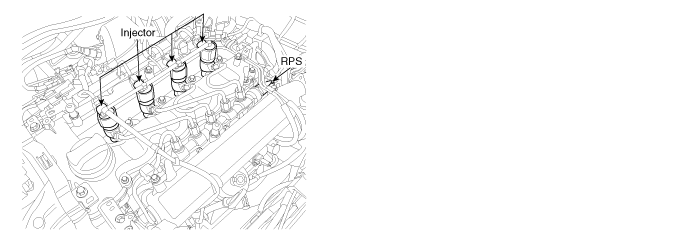
Injectors spray fuel in the highly compressed combustion chamber, and power generates through combustion process.
Fuel pressure is raised to 1600bar in common rail diesel engine for the purpose of making fuel into minute particles. And fuel devided into minute particles leads smoke reduction, high power generation, and improved fuel efficiency. To control pressure of 1600bar with solenoid, oil pressure surbo is applied. And injector solenoids is actuated by solenoid operating voltage raised to 80V with the method of current control.
Niddle valve inside of injector is located between A and B chamber. If applied pressure to B chamber is relived by injector solenoid, niddle valve is raised by the pressure of A chamber then, fuel is injected. If same pressure is applied to A and B chamber, niddle valve closes by the elasticity then, fuel injection stops.
As electronically controlled injector is applied instead of mechanical injector, pilot and post injection, injeciton duration and quantity control are achieved. And engine performance is improved by these control.
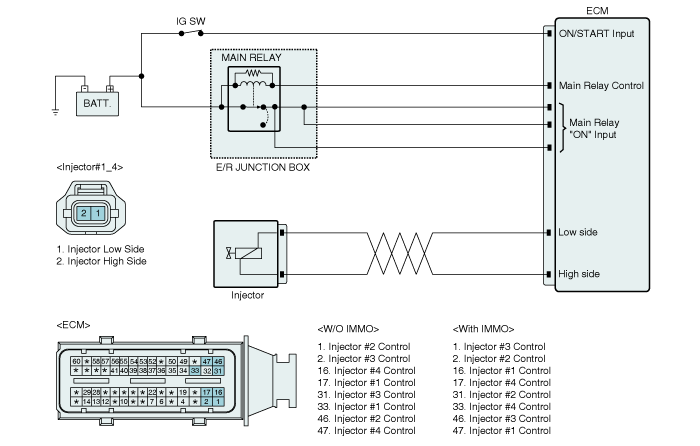
P0201 is set when no current is detected in injector power and control circuit at injector #1 operating condition. This code is due to open in injector circuit or open in injector component coil.
Item | Detecting Condition | Possible Cause | ||
DTC Strategy | ● Current monitoring | ● Open in injector circuit ● Injector component | ||
Enable Conditions | ● IG KEY "ON" | |||
Threshold Value | ● Open in injector circuit | |||
Diagnostic Time | ● Immediately | |||
Fail Safe | Fuel cut | NO | ||
EGR Off | NO | |||
Fuel Limit | YES | |||
Check Lamp | YES | |||
Injector Component Resistance | Injector Operating Voltage | Injector Operating Current | Injector Control Type |
0.255Ω±0.04 (20℃). | 80V | Peak current : 18±1A Hold in current : 12±1A Recharging current : 7A | Current control |


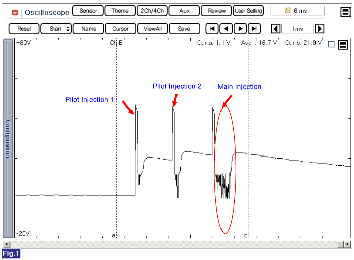
Fig.1) Injector operating waveform at Low side, It shows 2 pilot and 1 main injection.
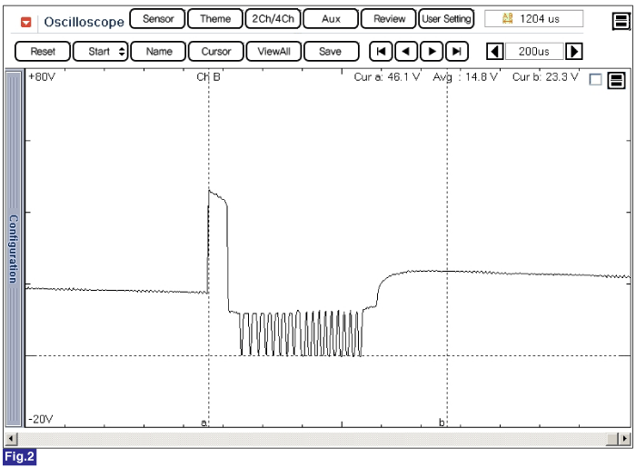
Fig.2) Magnified waveform of main injection at Fig.1)
Electrical systems consist of a lot of harness and connectors, poor connection of terminals can cause various problems and damge of component.
Perform checking procedure as follows.
Check damage of harness and terminals : Check terminals for contact resistance, corrosion and deformation.
Check connecting condition of ECM and component connector : Check terminal seperation, damage of locking device and connecting condition between terminal and wiring.
Disconnect the pin which requires checking at male connector and insert it to the terminal at female connector for checking connecting condition. ( after checking, reconnect the pin at correct position. )
Is the problem found?
 | ▶ Repair the trouble causing part and go to "Verification of Vehicle Repair". |
 | ▶ Go to "Power Circuit Inspection". |
Check open in power circuit(High side)
IG KEY "OFF", ENGINE "OFF".
Disconnect injector #1 connector and ECM connector.
Check continuity between high side terminal of injector #1 harness connector and ECM harness connector.
Specification : Continuity (below 1.0Ω )
Is the measured resistance within the specification?
 | ▶ Go to "Control Circuit Inspection". |
 | ▶ Repair open in injector #1 power circuit and go to "Verification of Vehicle Repair". |
Check open in control circuit(Low side)
IG KEY "OFF", ENGINE "OFF".
Disconnect injector #1 connector and ECM connector.
Check continuity between low side terminal of injector #1 harness connector and low side terminal of ECM harness connector.
Secification : Continuity (below 1.0Ω )
Is the measured resistance within the specification?
 | ▶ Go to "Component Inspection". |
 | ▶ Repair open in injector #1 control circuit and go to "Verification of Vehicle Repair". |
Check injector component resistance
IG KEY "OFF", ENGINE "OFF".
Disconnect injector connector.
Measure the resistance between high side terminal and low side terminal of injector connector. (component side).
Specification : 0.255Ω±0.04 (20°C).
Is the measured resistance(of injector solenoid) within the specification?
 | ▶ Go to "Verification of Vehicle Repair". |
 | ▶ Replace injector and go to "Verification of Vehicle Repair". |
Replacing injectors, peculiar IQA code of each injector should be inputted to ECM.
Perform this process using "Injector data input" function on GDS, Refer to P1670, P1671 for more detailed information.
After a repair, it is essential to verify that the fault is corrected.
After connecting GDS select "Diagnostic Trouble Codes(DTCs)" mode to and then clear DTC.
Drive the vehicle within DTC Enable conditions in General information.
After selecting "Diagnostic Trouble Codes(DTCs)" mode and check DTC is recorded again.
Are any DTCs recorded ?
 | ▶ Go to the DTC guide of recorded NO. in GDS. |
 | ▶ System operates within specification. |