Measure the waveform of ACV


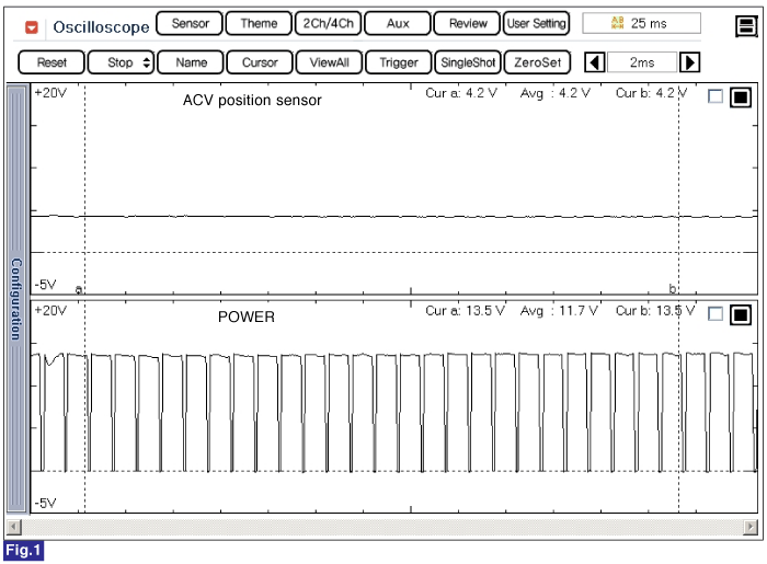
Fig.1) Waveform of Throttle Actuator(ACV) at IDLE - Not Operation status.
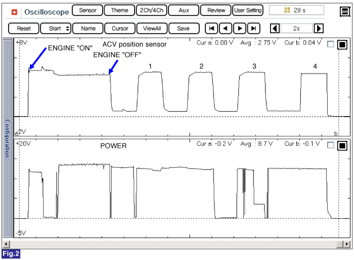
Fig.2) Waveform of Throttle Actuator(ACV) after Engine "OFF".

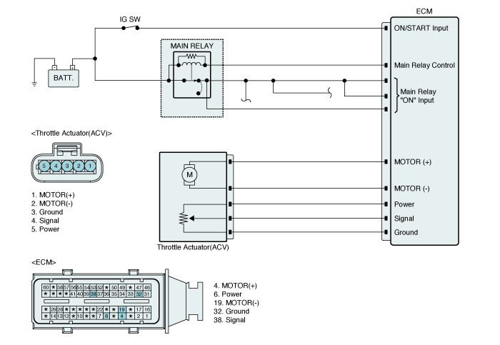
Throttle Control actuator(ACV) helps EEGR actuator in EGR control as controlling throttle flap position with the method of duty control. In EURO 3 diesel engine, precise EGR control is more difficult than in EURO 4 engine. Even though EGR actuator opens exhaust gas outlet fully, it is difficult for exhaust gas to be inhaled at intake manifold because intake air is already exist to be inhaled at there in EURO 3 engine. However in EURO 4 engine, controlling throttle flap position, it is possible to regulate the differential pressure between exhaust and intake air. With the control of the differential pressure, the amount of exhaust air to be recirculated is regulated. Besides, When turning engines OFF, Throttle control actuator cuts intake air to prevent dieselling.(In spite of turning engine OFF, engine does not stop and runs for a while due to rotating inertia of engine and fuel leakage at injector nozzle. )
P0122 is set when the voltage below 200mV - minimum output voltage of ACV - is detected for more than 1.0 sec. This code is due to short/open in ACV circuit or ACV, ECM.
Item | Detecting Condition | Possible Cause | ||
DTC Strategy | ● ACV POSITION MONITORING | ● ACV circuit ● ACV ● ECM | ||
Enable Conditions | ● IG KEY "ON" | |||
Threshold Value | ● Output signal below the minimum value.( below 200mV ) | |||
Diagnostic Time | ● 1000ms | |||
Fail Safe | Fuel Cut | NO | ||
EGR Off | NO | |||
Fuel Limit | NO | |||
Check Lamp | NO | |||
RESISTANCE | FREQUENCE | OPERATING VOLTAGE |
APPROX. 4.3Ω (20℃) | 400 ~ 16000 Hz | 12V |
OPERATING STANDARD RANGE | OPERATING TEMPERATURE | OPERATING VOLTAGE |
82° | -40 ~ 140 ℃ | 5V |


Fig.1) Waveform of Throttle Actuator(ACV) at IDLE - Not Operation status.
Fig.2) Wavrform of Throttle Actuator(ACV) after Engine "OFF".
Connect GDS to Data Link Connector (DLC).
Warm engine up to normal operating temperature.
Measure the waveform of ACV


Fig.1) Waveform of Throttle Actuator(ACV) at IDLE - Not Operation status.
Fig.2) Waveform of Throttle Actuator(ACV) after Engine "OFF".
Electrical systems consist of a lot of harness and connectors, poor connection of terminals can cause various problems and damge of component.
Perform checking procedure as follows.
Check damage of harness and terminals : Check terminals for contact resistance, corrosion and deformation.
Check connecting condition of ECM and component connector : Check terminal seperation, damage of locking device and connecting condition between terminal and wiring.
Disconnect the pin which requires checking at male connector and insert it to the terminal at female connector for checking connecting condition. ( after checking, reconnect the pin at correct position. )
Is the problem found?
 | ▶ Repair the trouble causing part and go to "Verification of Vehicle Repair". |
 | ▶ Go to "Power Circuit Inspection ". |
IG KEY "OFF", ENGINE "OFF".
Disconnect Thropttle Actuator(ACV) connector.
IG KEY "ON".
Measure the voltage between Power terminal of position sensor in ACV harness connector and chassis ground.
Specification : 4.8V~5.1V
Is the measured voltage within the specification?
 | ▶ Go to "signal circuit Inspection" procedure. |
 | ▶ Repair open or short in power circuit and go to "Verification of Vehicle Repair". |
IG KEY "OFF", ENGINE "OFF".
Disconnect Thropttle Actuator(ACV) connector.
IG KEY "ON".
Measure the voltage between Signal terminal of position sensor in ACV harness connector and chassis ground.
Specification : 4.8V~5.1V
Is the measured voltage within the specification?
 | ▶ Go to "ground circuit Inspection" procedure. |
 | ▶ Repair open or short in Signal circuit and go to "Verification of Vehicle Repair". |
IG KEY "OFF", ENGINE "OFF".
Disconnect Thropttle Actuator(ACV) connector.
IG KEY "ON".
Measure the voltage between Ground terminal of position sensor in ACV harness connector and chassis ground.
Specification : below 0.3V
Is the measured voltage within the specification?
 | ▶ Go to "Component Inspection" procedure. |
 | ▶ Repair open or short in Signal circuit and go to "Verification of Vehicle Repair". |
IG KEY "OFF", ENGINE "OFF".
Disconnect ACV connector.
Measure resistance between Power terminal and ground terminal of ACV.
Specification : Approx. 22.8KΩ (20℃)
Is the measured resistance within the specification?
 | ▶ Substitute with a known-good ECM and check for proper operation. If the problem is corrected, replace ECM as necessary and then,Go to "Verification of Vehicle Repair" procedure. |
 | ▶ Replace ACV as necessary and then, Go to "Verification of Vehicle Repair" procedure. |
After a repair, it is essential to verify that the fault is corrected.
After connecting GDS select "Diagnostic Trouble Codes(DTCs)" mode to and then clear DTC.
Drive the vehicle within DTC Enable conditions in General information.
After selecting "Diagnostic Trouble Codes(DTCs)" mode and check DTC is recorded again.
Are any DTCs recorded ?
 | ▶ Go to the DTC guide of recorded NO. in GDS. |
 | ▶ System operates within specification. |