5.
Read "DTC Status" parameter.
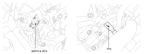
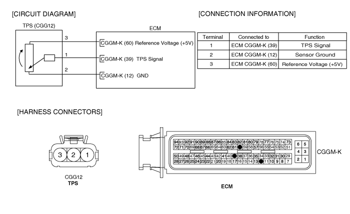
The Throttle Position Sensor (TPS) is mounted on the throttle body and detects the opening angle of the throttle plate.
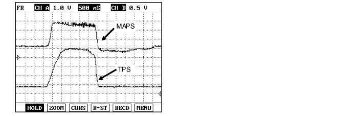
The TPS has a variable resistor (potentiometer) whose characteristic is the resistance changing according to the throttle angle. During acceleration, the TPS resistance between the reference 5V and the signal terminal decreases and output voltage increases; during deceleration, the TPS resistance increases and TPS output voltage decreases.
The ECM supplies a reference 5V to the TPS and the output voltage increases directly with the opening of the throttle valve. The TPS output voltage will vary from 0.2~0.8V at closed throttle to 4.3~4.8V at wide-open throttle.
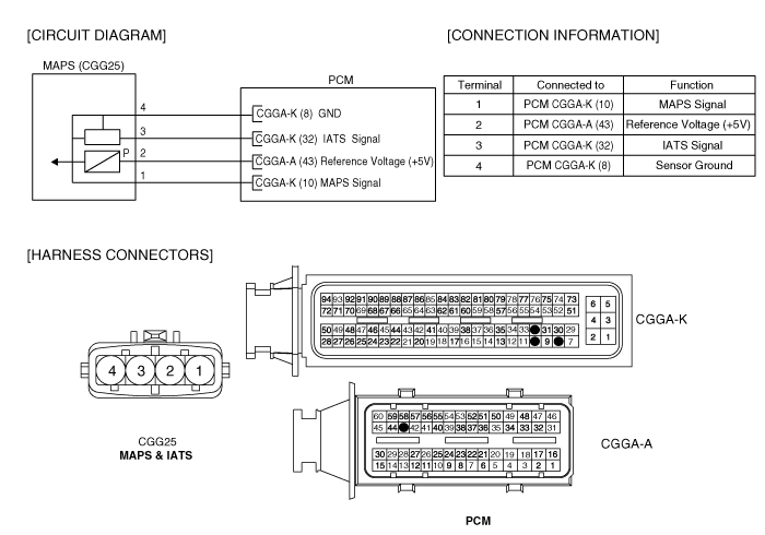
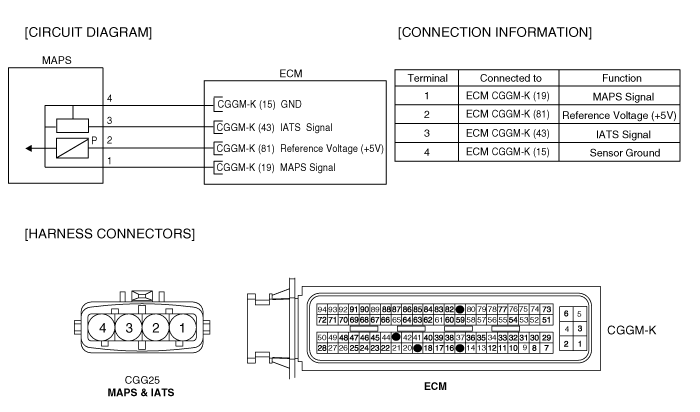
The ECM determines operating conditions such as idle (closed throttle), part load, acceleration/deceleration, and wide-open throttle from the TPS. Also The ECM uses the Mass Air Flow Sensor (MAFS) or Manifold Absolute Pressure Sensor (MAPS) signal along with the TPS signal to adjust fuel injection duration and ignition timing.
If the sensor input value of TPS is lower or higher than the threshold value which is depending on MAF(MAP) more 300sec, PCM sets DTC P0068.
Item | Detecting Condition | Possible Cause |
DTC Strategy | ● Rationality check (Correlation of actual and secondary load) | ● Poor connection ● TPS ● MAFS(MAPS) |
Enable Conditions | ● Correction factor for secondary load 〉 1.2 or Correction factor for secondary load 〈 0.8 | |
Threshold Value | ● Time for secondary load adaptation 〉 300s | |
Diagnostic Time | ● 1sec | |
MIL ON Condition | ● 3 driving cycle |
ITEM | Specification |
TPS Resistance(kΩ) | 2kΩ ± 20% (20℃) |
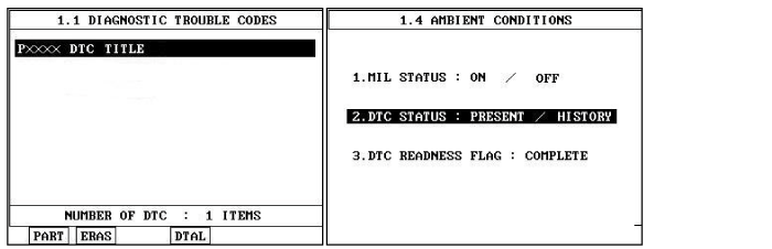
Connect scantool to Data Link Connector(DLC).
IG "ON".
Select "Diagnostic Trouble Codes(DTCs)" mode, and then Press F4(DTAL) to check DTC'sinformation from the DTCs menu
Confirm that "DTC Readiness Flag" indicates "Complete". If not, drive the vehicle within conditionsnoted in the freeze frame data or enable conditions noted in the DTC detecting condition.
Read "DTC Status" parameter.
Is parameter displayed "History(Not Present) fault"?
History fault : DTC occurred but has been cleared.
Present fault : DTC is occurring at present time.

▶ Fault is intermittent caused by poor contact in the sensor’s and/or ECM’s connector or wasrepaired and ECM memory was not cleared. Thoroughly check connectors for looseness,poor connection, bending, corrosion, contamination, deterioration, or damage.Repair or replace as necessary and then go to "Verification of Vehicle Repair" procedure.

▶ Go to "Terminal & Connector Inspection" procedure
Many malfunctions in the electrical system are caused by poor harness and terminals. Faults can also be caused by interference from other electrical systems, and mechanical or chemical damage.
Thoroughly check connectors for looseness, poor connection, bending, corrosion, contamination, deterioration, or damage.
Has a problem been found?
▶ Repair as necessary and go to "Verification of vehicle Repair" procedure.
▶ Go to "Component inspection" procedure.
Check TPS
Key "OFF". (Don't disconnect sensors.)
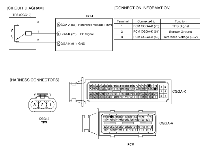
Select "vehicle scopemeter" in the menu, and connect channel A of scantool with terminal 1 of TPS harness connector.
Connect channel B of scantool with terminal 1 of MAPS harness connector.
Engine start. And check the signal waveforms with stepping on accelerator pedal.
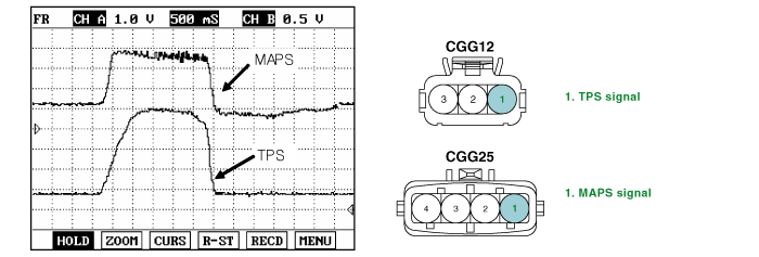
Is the signal waveform within specifications?
▶ Many malfunctions in the electrical system are caused by poor harness(es) and terminals. Faults can also be caused by interference from other electrical systems, and mechanical or chemical damage. So, check poor connections and the related circuit between ECM and component thoroughly. Repair as necessary and go to "Verification of Vehicle Repair" procedure.
▶ Substitute the sensor which outputs abnormal waveform with a known-good sensor and check for proper operation. If the problem is corrected, replace the sensor and then go to "Verification of Vehicle Repair" procedure.
After a repair, it is essential to verify that the fault has been corrected.
Connect scan tool and select "Diagnostic Trouble Codes(DTCs)" mode.
Press F4(DTAL) and confirm that "DTC Readiness Flag" indicates "Complete".
If not, drive the vehicle within conditions noted in the freeze frame data or enable conditions.
Read "DTC Status" parameter.
Is parameter displayed "History(Not Present) fault"?
▶ System performing to specification at this time. Clear the DTC.
▶ Go to the applicable troubleshooting procedure.
