Monitor "Alternator duty cycle, PWM signal" parameter on GDS

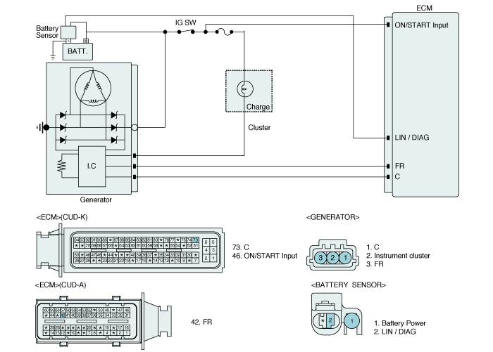
ISG System has alternator in which there is a communication regulator in order to compensate current loss resulting from repetitive starting. The alternator is duty controlled as current control by ECM with the battery voltage, current, temperature information from battery sensor. The more electrical load, the higher duty output.
ECM set DTC P0620 If it is open or short in Control circuit of alternator. If this DTC is set, Idle stop is not performing.
Item | Detecting Condition | Possible cause |
DTC Strategy | ● Signal check | ● Open or Short in harness ● Poor connection or damaged harness |
Enable Conditions | ● Desired alternator voltage duty cycle ≥ 3.12%, ≤ 94.5% ● Engine speed >240rpm ● Battery voltage <16V, >10.73V | |
Threshold value | ● Open or Short circuit | |
Diagnosis Time | ● 1sec | |
MIL On Condition | ● DTC only(Idle stop forbidden) |


Idle Status

Electrical Load (Head Lamp and Defrost are ON
Duty(+) from FR terminal is increased if electrical loads are ON (Head Lamp and Defrost are ON)
ECM controls generation of alternator with duty from FR terminal when electrical Loads turn on
Connect GDS to Data Link Connector(DLC).
Engine start.
Monitor "Alternator duty cycle, PWM signal" parameter on GDS

Are the parameters displayed correctly ?
 | ▶ Fault is intermittent caused by poor contact in the sensor’s and/or ECM’s connector or was repaired and ECM memory was not cleared. Thoroughly check connectors for looseness, poor connection, bending, corrosion, contamination, deterioration, or damage. Repair or replace as necessary and go to "Verification of vehicle Repair" procedure. |
 | ▶ Go to "Terminal & Connector Inspection" procedure |
Many malfunctions in the electrical system are caused by poor harness and terminals. Faults can
also be caused by interference from other electrical systems, and mechanical or chemical damage.
Thoroughly check connectors for looseness, poor connection, bending, corrosion, contamination,
deterioration, or damage.
Has a problem been found?
 | ▶ Repair as necessary and go to "Verification of vehicle Repair" procedure |
 | ▶ Go to "FR terminal Circuit Inspection" procedure. |
With ignition OFF, disconnect alternator connector
IG KEY "ON" & ENG "OFF"
Measure voltage between FR terminal of the alternator harness connector and chassis ground.
Specification : Approx. 9~11V
Is voltage within the specification?
 | ▶ Go to "C terminal Circuit Inspection" procedure. |
 | ▶ Repair as necessary and go to "Verification of Vehicle Repair" procedure. |
With ignition OFF, disconnect alternator connector
IG KEY "ON" & ENG "OFF"
Measure voltage between C terminal of the alternator harness connector and chassis ground.
Specification Approx. 0.8V
Is voltage within the specification?
 | ▶ Go to "Component inspection" procedure. |
 | ▶ Repair as necessary and go to "Verification of Vehicle Repair" procedure. |
IG "OFF".
Select "vehicle scopemeter" in the menu, and connect channel A of GDS with FR terminal of Alternator harness connector.
Connect Channel B of GDS with C terminal of Alternator harness connector.
Engine start. And check the signal waveforms.(Compare the signal waveform of electrical loads ON with OFF)
Specification : Refer to Signal Waveform & Data
Is the measured signal waveforms of Alternator normal?
 | ▶ Go to "Alternator check" procedure. |
 | ▶ Substitute with a known - good ECM and check for proper operation. If the problem is corrected, replace ECM and go to "Verification of Vehicle Repair" procedure. |
IG KEY "OFF".
Check the tension of alternator belt.
Check corrosion, damage or looseness of Battery terminal and Alternator terminal.
Engine start.
Operate electrical parts(Head lamp, Defoger, etc).
Measure the voltage at 2000rpm.
Specification : Approx 12.5V ~ 14.5V
Is the measured voltage within specification ?
 | ▶ Many malfunctions in the electrical system are caused by poor harness(es) and terminals. Faults can also be caused by interference from other electrical systems, and mechanical or chemical damage. So, check poor connections and the related circuit between ECM and component thoroughly. Repair as necessary and go to "Verification of Vehicle Repair" procedure. |
 | ▶ Substitute with a known - good Alternator and check for proper operation. If the problem is corrected, replace Alternator and go to "Verification of Vehicle Repair" procedure. |
After a repair, it is essential to verify that the fault has been corrected.
Connect scantool and select "DTC" button.
Press "DTC Status" button and confirm that "DTC Readiness Flag" indicates "Completed". If not, drive the vehicle within conditions noted in the freeze frame data or enable conditions
Read "DTC Status" parameter
Is parameter displayed "History(Not Present) fault"?
 | ▶ System performing to specification at this time. Clear the DTC |
 | ▶ Go to the applicable troubleshooting procedure. |