Read "DTC Status" parameter.

Many control units have applied to vehicle as it becomes more eletrolnical. These units control their own system based on information from diverse sensors. Therefore necessity of common use of diverse sensor information and importance of stable power supply are gathering strength. Battery sensor is mounted on battery (-) terminal. It transmits battery voltage, current, temperature information to ECM. ECM controls generating voltage by duty cycle based on these signals.
ECM sets this code when the battery charging current from battery sensor is too low.
Item | Detecting Condition | Possible cause |
DTC Strategy | ● Signal Monitoring | ● Poor connection ● Open or short in charging system ● Faulty charging system ● Faulty ECM |
Enable Conditions | ● IG "ON" ● No error related to LIN communication | |
Threshold value | ● Battery charging current < Calibration ● State of Charge(SOC) < Calibration | |
Diagnosis Time | ● 60sec | |
MIL On Condition | ● NO MIL ON(DTC only) |
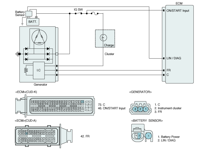
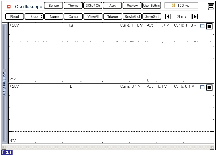
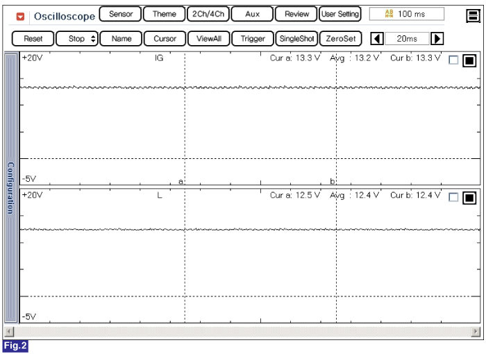
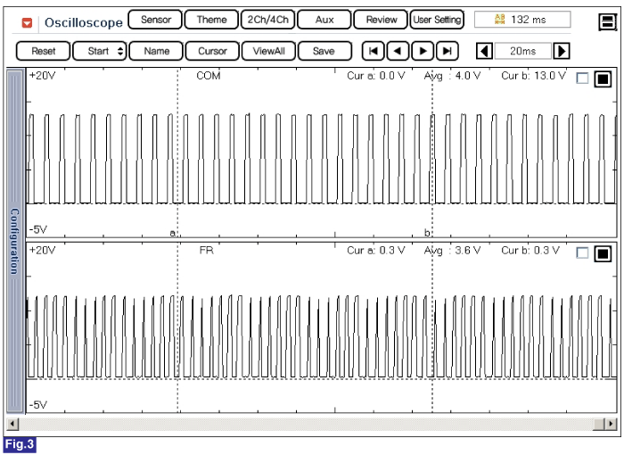
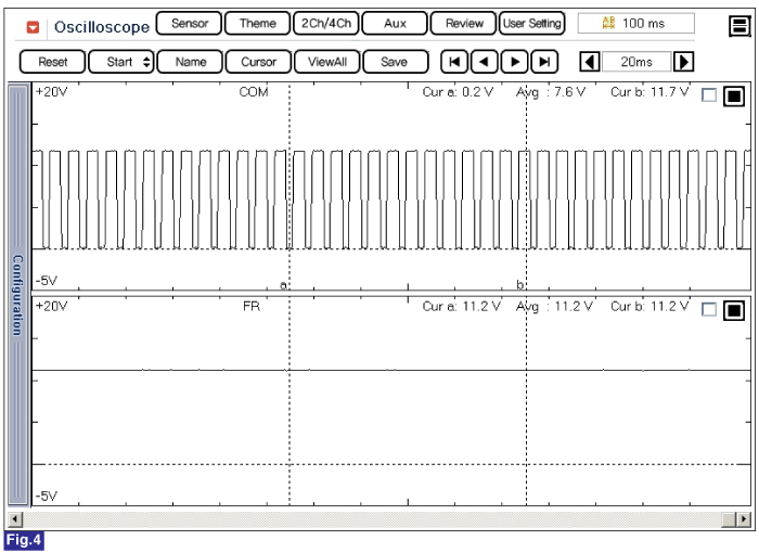
Fig .1) Normal waveforms of IG, L terminal of alternator during charge warning lamp is ON
Fig .2) Normal waveforms of IG, L terminal of alternator during charge warning lamp is OFF
Fig. 3) Normal waveforms of COM, FR terminal of alternator at idle.
Fig. 4) Normal waveforms of COM, FR terminal of alternator under connector disconnected condition.
Connect scantool to Data Link Connector(DLC).
IG "ON".
Select "DTC" button, and then Press "DTC Status" to check DTC's information from the DTCs menu.
Read "DTC Status" parameter.

Is parameter displayed "Present fault"?
 | ▶ Go to "Terminal and Connector inspection" procedure. |
 | ▶ Fault is intermittent caused by poor contact in the sensor’s and/or ECM’s connector or was repaired and ECM memory was not cleared. Thoroughly check connectors for looseness, poor connection, bending, corrosion, contamination, deterioration, or damage. Repair or replace as necessary and go to "Verification of vehicle Repair" procedure. |
Many malfunctions in the electrical system are caused by poor harness and terminals. Faults can also be caused by interference from other electrical systems, and mechanical or chemical damage.
Thoroughly check connectors for looseness, poor connection, bending, corrosion, contamination, deterioration, or damage.
Has a problem been found?
 | ▶ Repair as necessary and go to "Verification of Vehicle Repair" procedure |
 | ▶ Go to "System Inspection" procedure. |
Engine starts.
Maintain ENG RPM 2,500RPM over 2 minutes.
Measure voltage between the battery terminal(+) and the battery terminal(-).
Specification : Approx. 12.5 ~ 14.7V
Is the measured voltage within specification?
 | ▶ Check for Battery State, repair as necessary and go to "Verification of Vehicle Repair" procedure. |
 | ▶ Check that the tension of drive belt, ENG RPM, fuse, terminal of battery, all terminals of generator are in good condition and Check for damaged harness and poor connection between generator and battery. If OK repair or replace generator and then go to "Verification of vehicle Repair" procedure. |
After a repair, it is essential to verify that the fault has been corrected.
Connect scantool and select "DTC" button.
Press "DTC Status" button and confirm that "DTC Readiness Flag" indicates "Completed". If not, drive the vehicle within conditions noted in the freeze frame data or enable conditions
Read "DTC Status" parameter
Is parameter displayed "History(Not Present) fault"?
 | ▶ System performing to specification at this time. Clear the DTC |
 | ▶ Go to the applicable troubleshooting procedure. |