Monitor "battery sensor" parameter on GDS.


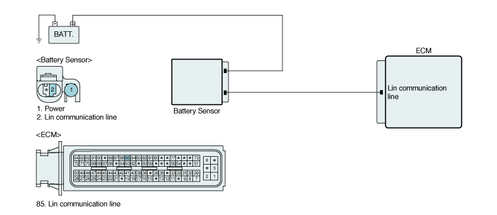
LIN technology is , a serial communication system which is used for communicating only one signal, developed to substitute CAN network, Normally used for multi signal communiction. It is only single wire to make LIN communiction in order to make simple network that is not important speed.
In case of ISG system, ECM receives battery infromation such as battery voltage, current and temperature etc.) through the LIN.
With the information received through the LIN, ECM decides alternator control, idle stop and auto start by receiving battery information.
ECM sets this code when there is an error in LIN communication line.
Item | Detecting Condition | Possible Cause |
DTC Strategy | ● Signal Monitoring | ● Open or short in LIN communication line |
Enable Conditions | ● - | |
Threshold Value | ● Framing error | |
Diagnostic Time | ● Continuous | |
MIL ON Condition | ● DTC only(Idle stop forbidden) |


Fig.1) Signal waveforms of battery sensor
Connect GDS to Data Link Connector(DLC).
Engine start.
Monitor "battery sensor" parameter on GDS.

Are the parameters displayed correctly ?
 | ▶ Fault is intermittent caused by poor contact in the sensor’s and/or ECM’s connector or was repaired and ECM memory was not cleared. Thoroughly check connectors for looseness, poor connection, bending, corrosion, contamination, deterioration, or damage. Repair or replace as necessary and go to "Verification of vehicle Repair" procedure. |
 | ▶ Go to "Terminal & Connector Inspection" procedure. |
Many malfunctions in the electrical system are caused by poor harness and terminals.
Faults can also be caused by interference from other electrical systems, and mechanical or chemical damage.
Thoroughly check connectors for looseness, poor connection, bending, corrosion, contamination, deterioration, or damage.
Has a problem been found?
 | ▶ Repair as necessary and go to "Verification of Vehicle Repair" procedure. |
 | ▶ Go to " Signal Circuit Inspection " procedure. |
IG "OFF" and disconnect battery sensor and ECM connector.
Check resistance between LIN terminal of battery sensor harness Connector and ECM harness connector.
Specification : Below 1.0Ω
Is the measured resistance within specification ?
 | ▶ Go to "Check short to battery in harness" as follows. |
 | ▶ Repair open in harnesses and go to "Verification of Vehicle Repair". |
IG "OFF" and disconnect battery sensor and ECM connector.
IG "ON"
Measure the voltage between LIN terminal of battery sensor harness connector and chassis ground.
Specification : Approx. 0V
Is the measured voltage within specification ?
 | ▶ Go to "Check short to ground in harness" as follows. |
 | ▶ Repair short to battery in harnesses and go to "Verification of Vehicle Repair". |
IG "OFF" and disconnect battery sensor and ECM connector.
Check resistance between LIN terminal of battery sensor harness Connector and chassis ground.
Specification : Infinity
Is the measured resistance within specification ?
 | ▶ Go to "Componect Inspection" as follows. |
 | ▶ Repair short to ground in harnesses and go to "Verification of Vehicle Repair". |
IG "OFF".
Connect probe to battery sensor to check signal waveform by using oscilloscope function.
IG "ON" and monitor signal waveform.
Specification : Signal waveform will be displayed as Signal Waveform & Data
Is the measured signal waveform O.K ?
 | ▶ Go to "Verification of Vehicle Repair" procedure. |
 | ▶ Substitute with a known - good battery sensor and check for proper operation. If the problem is corrected, replace battery sensor and go to "Verification of Vehicle Repair" procedure. |
After a repair, it is essential to verifying that the fault has been corrected.
Connect GDS and select "Diagnostic Trouble Codes(DTCs)" mode.
Using GDS, Clear DTC.
Operate the vehicle within DTC Enable conditions in General information.
Are any DTCs present ?
 | ▶ Go to the applicable troubleshooting procedure. |
 | ▶ System is performing to specification at this time. |