

The input(turbine) speed sensor outputs pulse-signals according to the revolutions of the input shaft of the transmission. The PCM/TCM determines the input shaft speed by counting the frequency of the pulses. This value is mainly used to control the optimum fluid pressure during shifting.
The PCM/TCM sets this code if an output pulse-signal is not detected, from the input speed sensor, when the vehicle is running faster than 30 km/h. The Fail-Safe function will be set by the PCM/TCM if this code is detected.
Item | Detecting Condition | Possible Cause |
DTC Strategy |
•
Circuit no signal |
•
Signal circuit is open or short
•
Sensor power circuit is open
•
Sensor ground circuit is open
•
Faulty INPUT SPEED SENSOR
•
Faulty PCM/TCM |
Enable Conditions |
•
TR switch D,3, 2, L range
•
Output Speed sensor >1000 rpm
•
Engine speed >3000 rpm | |
Threshold Value |
•
Input speed = 0rpm | |
Diagnostic Time |
•
More than 1sec | |
Fail Safe |
•
Locked into 3rd or 2nd gear.
•
Manual shifting is possibe (2 nd → 3 rd ,3 rd → 2 nd) |
Input shaft & Output shaft speed sensor
Type : Hall sensor
Current consumption : 22mA(MAX)
Sensor body and sensor connector have been unified as one.

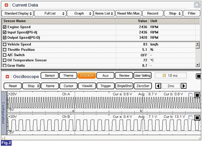
Fig 1) INPUT SIGNAL → LOW SPEED
Fig 2) INPUT SIGNAL → HIGH SPEED
