3.
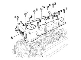
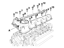
Remove the cylinder head cover (A).
Engine removal is not required for this procedure.
Remove the drive belt.
Remove the injector. (Refer to Injector in FL Group).
Remove the cylinder head cover (A).
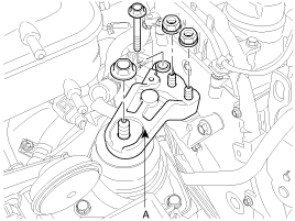
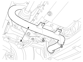
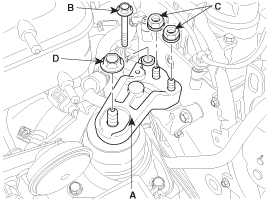
Remove the engine mounting support bracket.
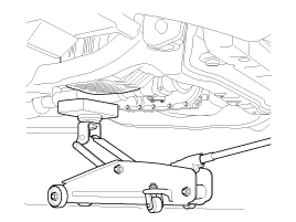
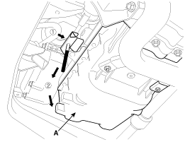
Set the jack to the engine oil pan
Disconnect the engine ground cable and then remove the engine mounting support bracket (A).
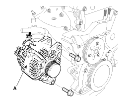
Remove the alternator (A).
Remove the water pump pulley (A).
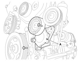
Remove the drive belt auto tensioner (A).
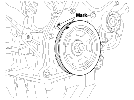
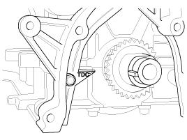
Turn the crankshaft pulley, and align its groove with timing mark "T" of the timing chain cover. (No.1 cylinder compression TDC position)
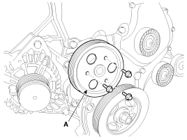
Remove the crankshaft pulley bolt (B) and crankshaft pulley (A).
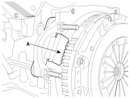
Use the SST(flywheel stopper, 09231-2A100)(A) to remove the crankshaft pulley bolt, after remove the starter.
Remove the oil gage guide.
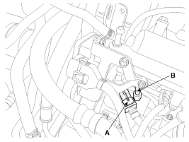
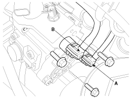
Disconnect the fuel pressure regulator valve connector (A).
Remove the high pressure fuel pipe (B) connecting the high pressure fuel pump with the common rail.
Remove the engine mounting insulator (B).
Remove the idler (A) and the timing chain cover plug (B).
Remove the high pressure fuel pump sprocket nut (C) after fixing the crank shaft.
Use flywheel stopper (SST No.: 09231-2A100) to remove the high pressure pump sprocket nut.
Replace O-ring of plug (B) with a new one when reinstalling the plug.
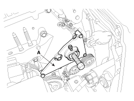
Disconnect the fuel feed tube (A) and the fuel return tube (B).
Unscrew the three high pressure fuel pump mounting bolts (C).
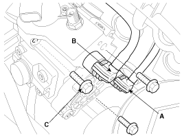
Install the high pressure fuel pump sprocket stopper (A) (SST No.: 09331-2A010) with rotating it clockwise.
Lift the RH side of the engine with a jack.
Install the high pressure fuel pump remover (SST No.:09331-2A010) (A) with three mounting bolts (B).
Fix the high pressure fuel pump remover (SST No.:09331-2A010) (A) and sprocket stopper (C) with two fixing bolts (D).
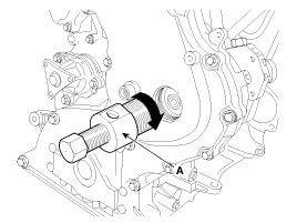
Rotate the bolt (E) of the high pressure fuel pump remover (SST No.:09331-2A010) (A) clockwise till the high pressure fuel pump is pushed out.
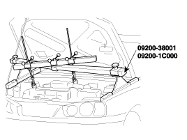
Install the engine support fixture and the adapter (SST No.: 09200-38001, 09200-1C000) on the engine hanger bracket.
Remove the intercooler pipe (A).
Remove the A/C compressor. (Refer to A/C compressor in HA group)
Remove the jack from oil pan.
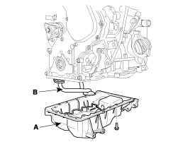
Remove the oil pan (A).
When removing the oil pan, use the SST(09215-3C000) in order not to damage the surface between the cylinder block and the oil pan.
Insert the SST between the oil pan and the ladder frame by tapping it with a plastic hammer in the direction of ① arrow.
After tapping the SST with a plastic hammer along the direction of ② arrow around more than 2/3 edge of the oil pan, remove it from the ladder frame.
Do not turn over the SST abruptly without tapping. It be result in damage of the SST.
Remove the oil strainer (B).
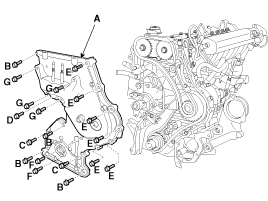
Remove the timing chain cover (A)
Remove thoroughly sealant and oil etc left at the sealing surface after remove the chain cover and oil pan. (If any impurities are left at the sealing face, oil may leak after reassembly even with the sealant application.)
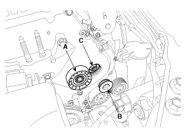
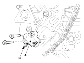
Remove the timing chain "C" auto tensioner(A).
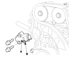
Before removing auto-tensioner, install a set pin (B) (2.5 mm steel wire) after compressing the tensioner.
Remove the timing chain "C" lever (A) and the timing chain guide "1" (B).
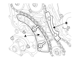
Remove the timing chain guide "2" (A).
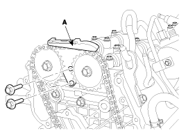
Remove the timing chain "C" (A).
Remove the timing chain "A" auto tensioner (A).
Before removing auto-tensioner, install a set pin (B) (2.5 mm steel wire) after compressing the tensioner.
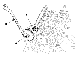
Remove timing chain "A" lever (A) and the timing chain guide "1" (B).
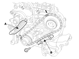
Remove the timing chain "A" (A)with high pressure pump sprocket (B) and crankshaft sprocket (C).
Remove the water pump (A).
Remove the timing chain case (A).
(Engine removal is required for this procedure)
Remove the camshaft sprocket.
Hold the portion (A) of the camshaft with a hexagonal wrench, and remove the bolt (C) with a wrench (B) and remove the camshaft sprocket.
Be careful not to damage the cylinder head and valve lifter with the wrench.
Engine removal is not required for this procedure.
Install the camshaft sprocket and tighten the bolt to the specified torque.
Temporarily install the camshaft sprocket bolt (C).
Hold the portion (A) of the camshaft with a hexagonal wrench, and tighten the bolt (C) with a wrench (B).
Tightening torque :
68.6 ~ 73.5N.m (7.0 ~ 7.5kgf.m, 50.6 ~ 54.2lb-ft)
Install the timing chain case (A) with new gasket.
(Engine removal is required for this procedure)
Tightening torque :
Bolt (B) : 24.5 ~ 30.4N.m (2.5 ~ 3.1kgf.m, 18.1 ~ 22.4lb-ft)
Bolt (C) :18.6 ~ 27.5N.m (1.9 ~ 2.8kgf.m, 13.7 ~ 20.3lb-ft)
Bolt (D) : 25.5 ~ 34.3N.m (2.6 ~ 3.5kgf.m, 18.8 ~ 25.3lb-ft)
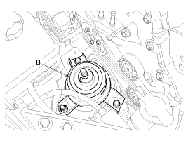
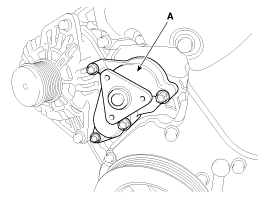
Install the water pump (A).
Tightening torque :
19.6 ~ 24.5N.m (2.0 ~ 2.5kgf.m, 14.5 ~ 18.1lb-ft)
Install the high pressure fuel pump after connecting the fuel feed tube (A) and the fuel return tube (B).
Tightening torque :
19.6 ~ 25.5N.m (2.0 ~ 2.6kgf.m, 14.5 ~ 18.8lb-ft)
Install the high pressure fuel pump under installing the high pressure fuel pump remover (SST No. : 09331 - 2A010) (A) because of maintaining tension of the timing chain.
Connect the fuel pressure regulator valve and install the high pressure pipe (B).
Tightening torque :
24.5 ~ 28.4N.m (2.5 ~ 2.9kgf.m, 18.1 ~ 21.0lb-ft)
Do not reuse the high pressure pipe.
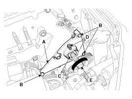
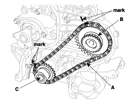
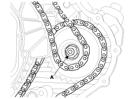
Set the key of crankshaft sprocket to be aligned with the timing mark of timing chain case. As a result of this, place the piston on No.1 cylinder at the top dead center on compression stroke.
After install timing chain "A" with high pressure pump sprocket (B) equipped at the crankshaft sprocket (C), and then install high pressure pump sprocket at the high pressure pump shaft.
The timing mark of high pressure pump sprocket should be aligned with timing mark on the timing chain case.
Pretighten the high pressure fuel pump sprocket nut.
Install timing chain "A" lever (A) and the timing chain guide "1" (B).
Tightening torque :
9.8 ~ 11.8N.m (1.0 ~ 1.2kgf.m, 7.2 ~ 8.7lb-ft)
Install the timing chain "A" auto tensioner (A) and then remove set pin (B).
Tightening torque :
9.8 ~ 11.8N.m (1.0 ~ 1.2kgf.m, 7.2 ~ 8.7lb-ft)
Align the timing mark (A) of camshaft sprocket on the vertical center line of crankshaft.
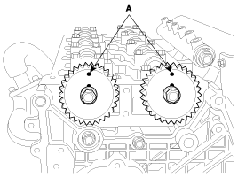
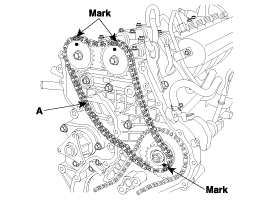
Install the timing chain "C" (A) as following procedure. High pressure pump sprocket → LH camshaft sprocket → RH camshaft sprocket
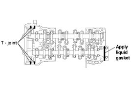
The timing mark of each sprockets should be matched with timing mark (color link) of timing chain at installing timing chain as shown below illustration.
Install the timing chain guide "2" (A).
Tightening torque :
9.8 ~ 13.7N.m (1.0 ~ 1.4kgf.m, 7.2 ~ 10.1lb-ft)
Install the timing chain "C" lever (A) and the timing chain guide "1" (B).
Tightening torque :
9.8 ~ 11.8N.m (1.0 ~ 1.2kgf.m, 7.2 ~ 8.7lb-ft)
Install the timing chain "C" auto tensioner (A) and then remove set pin (B).
Tightening torque :
9.8 ~ 11.8N.m (1.0 ~ 1.2kgf.m, 7.2 ~ 8.7lb-ft)
Install the high pressure pump sprocket nut (A).
Tightening torque :
64.7 ~ 74.5N.m (6.6 ~ 7.6kgf.m, 47.7 ~ 55.0lb-ft)
Use the SST(flywheel stopper, 09231-2A100)(A) to tighten the high pressure pump sprocket nut, after remove the starter.
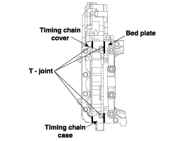
Apply liquid gasket evenly to the mating surface of timing chain cover.
Standard liquid gasket : LOCTITE 5900
Check that the mating surfaces are clean and dry before applying liquid gasket.
Assemble the timing chain cover in 5 minutes after applying the liquid gasket.
Apply liquid gasket in a 3mm wide bead without stopping.
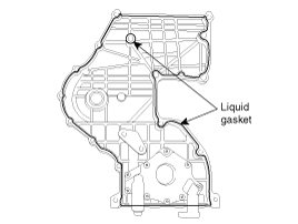
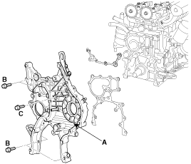
Install the timing chain cover (A).
Tightening torque :
Bolt (B, C, F) :
19.6 ~ 26.5N.m (2.0 ~ 2.7kgf.m, 14.5 ~ 19.5lb-ft)
Bolt (D, E) : 9.8 ~ 11.8N.m (1.0 ~ 1.2kgf.m, 7.2 ~ 8.7lb-ft)
Bolt (G) : 42.2 ~ 54.0N.m (4.3 ~ 5.5kgf.m, 31.1 ~ 39.8lb-ft)
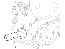
Install the front oil seal by using SST(09231-2A000, 09231-H1100) (A).
Install the oil strainer (B).
Tightening torque :
Bolts : 19.6 ~ 26.5N.m (2.0 ~ 2.7kgf.m, 14.5 ~ 19.5lb-ft)
Nuts : 9.8 ~ 11.8N.m (1.0 ~ 1.2kgf.m, 7.2 ~ 8.7lb-ft)
Apply liquid gasket evenly to the mating surface of oil pan.
Standard liquid gasket : LOCTITE 5900
Check that the mating surfaces are clean and dry before applying liquid gasket.
Apply liquid gasket in a 3mm wide bead without stopping.Assemble the oil pan in 5 minutes after applying the liquid gasket.
After assembly, wait at least 30 minutes before filling the engine with oil.
Apply liquid gasket to T-joint before assembling oil pan.
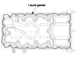
Install the oil pan.
Tightening torque :
9.8 ~ 11.8N.m (1.0 ~ 1.2kgf.m, 7.2 ~ 8.7lb-ft)
Set the jack to the engine oil pan
Install the engine support fixture and the adapter (SST No.: 09200-38001, 09200-1C000) on the engine hanger bracket.
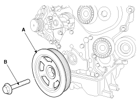
Install the crankshaft pulley (A) and crankshaft pulley bolt (B).
Tightening torque :
225.6 ~ 245.2N.m (23.0 ~ 25.0kgf.m, 166.4 ~ 180.8lb-ft)
Use the SST(flywheel stopper, 09231-2A100) to Install the crankshaft pulley bolt, after remove the starter.
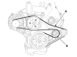
Install the drive belt tensioner (A).
Tightening torque :
25.5 ~ 30.4N.m (2.6 ~ 3.1kgf.m, 18.8 ~ 22.4lb-ft)
Install the water pump pulley (A).
Tightening torque :
9.8 ~ 11.8N.m (1.0 ~ 1.2kgf.m, 7.2 ~ 8.7lb-ft)
Install the alternator (A). (Refer to Alternator in EEB group)
Tightening torque :
38.2 ~ 58.8N.m (3.9 ~ 6.0kgf.m, 28.2 ~ 43.4lb-ft)
Install the drive belt (A) after releasing tension of the tensioner (B) with a wrench.
Install the engine mounting support bracket (A) and connect the engine ground cable.
Tightening torque :
Nut (D) : 68.6 ~ 93.2N.m (6.5 ~ 8.5kgf.m, 50.6~ 68.7lb-ft)
Bolt (B), Nut (C) : 49.0 ~ 63.7N.m (5.0 ~ 6.5kgf.m, 36.2 ~ 47.0lb-ft)
Remove the jack from oil pan
Install the cylinder head cover (A) with new head cover gasket.
Tightening torque :
1st : 3.9 ~ 5.9N.m (0.4 ~ 0.6kgf.m, 2.9 ~ 4.3lb-ft)
2st : 8.8 ~ 10.8N.m (0.9 ~ 1.1kgf.m, 6.5 ~ 8.0lb-ft)
Standard liquid gasket : LOCTITE 5900
Check that the mating surfaces are clean and dry before applying liquid gasket.
Apply liquid gasket in a 7mm (0.28in) wide bead without stopping.
Assemble the cylinder head cover in 5 minutes after applying the liquid gasket.
After assembly, wait at least 30 minutes before filling the engine with oil.
Apply liquid gasket to T-joint before assembling cylinder head cover.
Install the injectors. (Refer to Injector in FL Group)
