
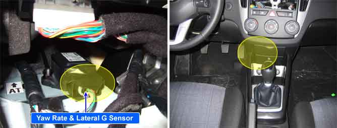
When the vehicle is turning, the yaw rate sensor detects the yaw rate electronically by the vibration change of plate fork inside the yaw rate sensor. If the yaw velocity reaches the specific velocity after it detects the vehicle's yawing, the ESP control is reactivated. The lateral G sensor senses the vehicle's lateral acceleration. A small element inside the sensor is attached to a deflectable leverarm by lateral acceleration. Direction and magnitude of lateral acceleration loaded to vehicle can be known by electrostatic capacity changing according to lateral acceleration. It interchanges signals with HECU through extra CAN line which is only used for communication between HECU and the sensor. In case of the vehicle with 4WD & ESP, G sensor is packaged with yaw rate & later G sensor.
A lateral acceleration reference signal is calculated from the wheel speeds, the steering angle and the yaw rate signals to observe the lateral acceleration sensor signal. The difference between the reference signal and the sensor signal is evaluated for failure detection.
A yaw rate reference signal is calculated from the wheel speeds, the steering angle and the lateral acceleration signals to observe the yaw rate sensor signal. The difference between the reference signal and the sensor signal, and the gradient of the measured sensor signal is evaluated for the failure detection. If the difference between estimated value and measured value of the sensor is larger than predefined value for predefined time, the failure is recognized. Plauibility faults (signals received which fall outside of the sensor characteristics) are also recognized.
Item | Detecting Condition | Possible cause | |
DTC Strategy |
•
Signal Monitoring | 1. Faulty Yaw Sensor 2. Open or short of Yaw Sensor | |
Case 1 | MonitoringPeriod |
•
Continuous (during stable driving) | |
Enable Conditions |
•
In case of stable driving, monitoring a suspicious mode if it is more than 3 m/s2 to the difference between measured lateral G sensor values and lateral G values estimated from other sensors. If suspicious mode is held on, a fault is set (max. 120sec) - During the possibility to observe the recognition time depends on the amount of failure. | ||
Case 2 | MonitoringPeriod |
•
Continuous (during standstill) | |
Enable Conditions |
•
In case of standstill, monitoring a fault if it is more than 7.0 m/s2 to the difference between previous lateral G offset and the mean of lateral G offset estimated from other sensors. | ||
Case3 | MonitoringPeriod |
•
Continuous (during driving) | |
Enable Conditions |
•
In case of straight and stable driving over 30kph, monitoring a fault if it is more than 2.5m/s2 to the difference between previous lateral G offset and mean of lateral G offset estimated from other sensors. | ||
Case4 | MonitoringPeriod |
•
Continuous (during driving) | |
Enable Conditions |
•
In case of stable driving, monitoring a suspicious mode if it is more than 3.5 deg to the difference between measured Yaw sensor values and Yaw values estimated from other sensors. If suspicious mode is held on,a fault is set. (max. 120sec) | ||
Case5 | MonitoringPeriod |
•
Continuous (during standstill) | |
Enable Conditions |
•
In case of standstill, monitoring a fault if it is more than 3deg/sec to the difference between previous Yaw offset and the mean of Yaw offset estimated from other sensors. | ||
Case6 | MonitoringPeriod |
•
Continuous (during driving) | |
Enable Conditions |
•
In case of straight and stable driving over 30kph, monitoring a fault if it is more than 3deg/sec to the difference between previous Yaw offset and mean of Yaw offset estimated from other sensors. | ||
Case7 | MonitoringPeriod |
•
Continuous (no under voltage fault after IGN On) | |
Enable Conditions |
•
llateral G sensor valuel > 15 m/s2 , - fault detection time: keep the value for 1s
•
Δlateral G sensor value > 11 m/s2 - fault detection time : keep the difference value for 120 ms
•
lYaw sensor Valuel > 30 deg/sec, for 5s on first standstill lYaw sensor Valuel > 95 deg/sec, for 1s on driving
•
ΔYaw sensor value > (10~25 deg/sec) - fault detection time: keep the difference value (ΔYaw sensor value) for 120 ms | ||
Case8 | MonitoringPeriod |
•
Continuous | |
Enable Conditions |
•
Monitoring a fault if it is more than 4.5m/s2 to the difference between longitudinal G sensor value and the mean of Yaw offset estimated from other sensors for more than 2s. | ||
Case9 | MonitoringPeriod |
•
Continuous (during standstill) | |
Enable Conditions |
•
llongitudinal G sensorl > 15 m/s2 , For moer than 800ms | ||
Fail Safe |
•
Inhibit the ESP control and allow the ABS/EBD control.
•
The ESP warning lamps are activated. | ||