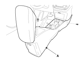
Remove the floor console assembly (A) after loosening the console mounting screws.
(Refer to the BD group - "Console")
Disconnect the negative (-) battery terminal.
Remove the floor console assembly (A) after loosening the console mounting screws.
(Refer to the BD group - "Console")

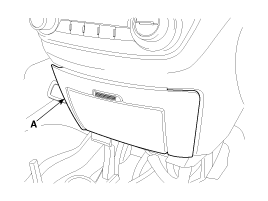
Remove the center facia lower try (A) after loosening the mounting screws.
Remove the body control module (A) after loosening 2 bolts and disconnecting connector.
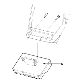
Install the body control module.
Install the center facia lower try.
Install the floor console assembly.

Pin NO. | Connector A | Connector B | Connector C |
1 | Battery Voltage | Auto Light Signal | Room Lamp |
2 | IGN1 | Auto Light (Ground) | - |
3 | Alternator 'L' | Rear Right Door Unlock Switch | Defogger Relay |
4 | Key In Switch | Rear Defogger Switch | Tail Lamp Relay |
5 | Speed Limit | Rear Fog Lamp Switch | Wiper Relay |
6 | Rear Left Door Lock Switch | Front Fog Lamp Switch | DRL Lock Relay 1 |
7 | Carsh Input | Auto Light (Power) | Dead Lock Relay 1 |
8 | Driver Door Unlock Switch | - | Horn Relay |
9 | Passenger Side Door Unlock Switch | - | Hazard Relay |
10 | Rear Wiper Switch | EMS | Key Illumination Lamp |
11 | - | Safety Power Window ECU | Driver Seat Belt Indicator |
12 | Ground | Power Window Relay | Ground(power) |
13 | IGN2 | Front Deicer Relay | Rear Fog Relay |
14 | Washer Switch | Head Lamp Relay | Diagnosis |
15 | INT Wiper Switch | Door Lock Relay 2 | Central Door Lock Indicator |
16 | Code Save | Security Indicator | Door Open Indicator |
17 | Rear Right Washer Switch | Front Fog Lamp Relay | |
18 | Tailgate Relay | Rear Wiper Relay | |
19 | Tailgate Handle Switch | Head Lamp Escort | |
20 | Driver Door Switch | Passenger Seat Belt Indicator | |
21 | Assist Door Switch | ||
22 | Rear Left Door Switch | ||
23 | Tailgate Door Switch | ||
24 | Hood Switch | ||
25 | Driver Door Key Lock Switch | ||
26 | Driver Door Key Unlock Switch | ||
27 | - | ||
28 | Tail Lamp Switch | ||
29 | INT Wiper Volume Switch | ||
30 | Speed Sensor | ||
31 | Auto Light Switch | ||
32 | Driver Seat Belt Switch | ||
33 | Head Lamp Switch | ||
34 | Assist Door Key Unlock Switch | ||
35 | Central Door Lock/unlock Switch | ||
36 | Assist Seat Belt Signal | ||
37 | Front Deicer Switch | ||
38 | MIST Switch | ||
39 | Rear Door Switch | ||
40 | - |
No | Input signal name | Logic state | ON/OFF voltage recognition LEVEL(V) | Remarks |
1 | B+ | ON = BAT | 9V~16V |
|
2 | IGN1 | ON = BAT (IGN KEY is ON or START position) | 7V or more/4V or less | BAT= BATTERY |
3 | IGN2 | ON = BAT (IGN KEY is ON position) | 7V or more/4V or less |
|
4 | Alt L | ON = BAT(starting state) | 7V or more/4V or less |
|
5 | Key In Switch | IN = BAT (KEY insertion state) | 7V or more/4V or less |
|
6 | Rear Left Door Switch | OPEN = GND | 1V or less/OPEN (Reference value: 4V or more) |
|
7 | Driver door switch | OPEN = GND | 1V or less/OPEN (Reference value: 4V or more) |
|
8 | Passenger side door Switch | OPEN = GND | 1V or less/OPEN (Reference value: 4V or more) |
|
9 | Driver door unlock switch | LOCK = OPEN, UNLOCK = GND | 1V or less/OPEN (Reference value: 4V or more) |
|
10 | Passenger side door Unlock Switch | LOCK = OPEN, UNLOCK = GND | 1V or less/OPEN (Reference value: 4V or more) |
|
11 | Center door lock/unlock switch | ON=GND | 1V or less/OPEN (Reference value: 4V or more) |
|
12 | Rear door switch | OPEN = GND | 1V or less/OPEN (Reference value: 4V or more) |
|
13 | Tail gate switch | OPEN = GND | 1V or less/OPEN (Reference value: 4V or more) |
|
14 | Hood Switch | OPEN = GND | 1V or less/OPEN (Reference value: 4V or more) |
|
15 | Driver door key lock switch | ON = GND | 1V or less/OPEN (Reference value: 4V or more) |
|
16 | Driver door key unlock switch | ON = GND | 1V or less/OPEN (Reference value: 4V or more) |
|
17 | Passenger door key unlock switch | ON = GND | 1V or less/OPEN (Reference value: 4V or more) |
|
18 | Front deicer switch | ON = GND | 1V or less/OPEN (Reference value: 4V or more) |
|
19 | Washer switch | ON = BAT | 7V or more/4V or less |
|
20 | Wiper INT switch | ON = BAT | 7V or more/4V or less |
|
21 | Wiper INT volume switch | 0V ~ 2.5V | - | 0Ω~ 50KΩ |
22 | Rear washer switch | ON = BAT | 7V or more/4V or less |
|
23 | Rear wiper Int switch | ON = BAT | 7V or more/4V or less |
|
24 | Rear defogger switch | ON = GND | 1V or less/OPEN (Reference value: 4V or more) |
|
25 | Tail switch | ON = GND | 1V or less/OPEN (Reference value: 4V or more) |
|
26 | L_Driver seat belt switch | Fasten = OPEN, Unfasten = GND | 1V or less/OPEN (Reference value: 4V or more) |
|
27 | Crash Input (Impact sensor) | ON = GND(at crash detection) | 1V or less/OPEN (Reference value: 4V or more) |
|
28 | Speed sensor | Speed input = PULSE(0~5V) | 1V or less/4V or more | OPEN COLLECTOR |
29 | Head lamp switch | ON = GND | 1V or less/OPEN (Reference value: 4V or more) |
|
30 | Front fog switch | ON = GND | 1V or less/OPEN (Reference value: 4V or more) |
|
31 | Rear fog switch | ON = GND | 1V or less/OPEN (Reference value: 4V or more) |
|
32 | Tail gate handle switch | ON = GND | 1V or less/OPEN (Reference value: 4V or more) |
|
33 | Code save unit | ON = GND | 1V or less/4V or more |
|
34 | Rear right door Unlock switch | LOCK = OPEN, UNLOCK = GND | 1V or less/OPEN (Reference value: 4V or more) |
|
35 | Rear left door Unlock switch | LOCK = OPEN, UNLOCK = GND | 1V or less/OPEN (Reference value: 4V or more) |
|
36 | Mist switch | ON = BAT | 7V or more/4V or less |
|
37 | Auto light sensor Signal | - | - |
|
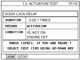
SCAN tool can operates all actuators controlled by BCM by force.
NO. | BCM DISPLAY |
1 | DOOR LOCK RELAY |
2 | DOOR UNLOCK RELAY |
3 | TAILGATE RELEASE RELAY |
4 | POWER WINDOW RELAY |
5 | WIPER RELAY |
6 | HAZARD RELAY (+RK) |
7 | BURGLAR HORN RELAY (+RK) |
8 | STARTER INHIBIT RELAY (+RK) |
9 | TAIL LAMP RELAY/DRL UNIT |
10 | HEAD LAMP RELAY |
11 | REAR FOG RELAY |
12 | FRONT DEICER RELAY |
13 | REAR DEFOGGER RELAY |
14 | DRIVER SEAT BELT INDICATOR |
15 | IGN KEY HOLE ILLUMINATION |
16 | ROOM LAMP |
It will be able to diagnose defects of BCM with scan tool quickly. Scan tool can operates actuator forcefully, input/output value monitoring and self diagnosis.
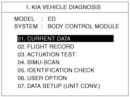
Select model and menu.
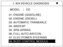
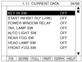
Select "Current data", if you will check current data of BCM. It provides power supply status, multi function status, lamp status, door status, lock system status, wiper, auto light status and so on.
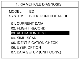
If you will check BCM data operation forcefully, select "Actuation test".
You can turn ON/OFF as below option function with the user option program.
LOCK / UNLOCK comfirming alarm: Alarm sound ON/OFF control when you LOCK/UNLOCK doors with transmitter.
Mechanical LOCKING system: Arm/Disarm ON/OFF when you lock the door with the mechanical key.
AUTO DOOR LOCK/UNLOCK system ON/OFF.
Vehicle speed gearing AUTO DOOR LOCK (more than 20km/h)
AUTO DOOR LOCK non application
Shift lever gearing AUTO DOOR LOCK
Driver seat AUTO DOOR LOCK
AUTO DOOR UNLOCK non application
All doors UNLOCK in the case of driver door UNLOCK
All doors UNLOCK in the case of IGN key seperation.
Riding & Getting off gearing
Seat installation state ON/OFF
Seat riding & getting off gearing ON/OFF
Column installation state ON/OFF
Column riding & getting off gearing ON/OFF
The BCM offers 1 items user option mode for a user convenience (AUTO DOOR LOCK)
It is able to set up the enable or disable of AUTO DOOR LOCK function or AUTO DOOR LOCK operation vehicle speed when using it.
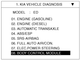
Select option "ED" and press ENTER.
Select option "BODY CONTROL MODULE" and press ENTER.
Select option "USER OPTION" and press ENTER.
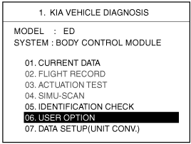
Select option "AUTO DOOR LOCK STATUS by using the direction button(▲ / ▼).
Select the parameter by using the direction button(◀ / ▶) and press ENTER to save it.
(Disable / FIXING)