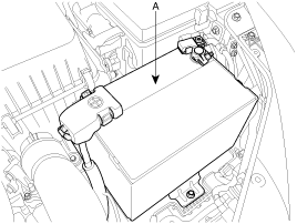
Disconnect the negative battery terminal and remove the battery (A).
Use fender covers to avoid damaging painted surfaces.
To avoid damage, unplug the wiring connectors carefully while holding the connector portion.
Mark all wiring and hoses to avoid misconnection.
Disconnect the negative battery terminal and remove the battery (A).

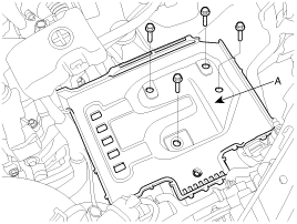
Remove the battery tray (A) after removing the bolts.
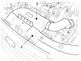
Remove the radiator grill upper cover (A) and the air duct (B).
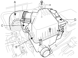
Remove the air intake hose (A) and the air cleaner assembly (B) after disconnecting the connector (C) and the ECM connector (D).
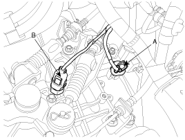
Disconnect the vehicle speed sensor connector (A) and the back lamp switch connector (B).
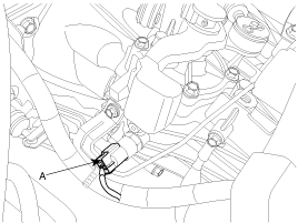
Disconnect the neutral switch connector (A).
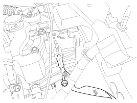
Remove the ground wire by removing a bolt.
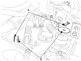
Remove the snap pins (A) and clips (B).
Remove the control cable bracket by removing bolts (3ea).
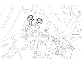
Remove the CKP sensor by removing a bolt.
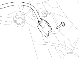
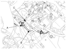
After removing the clip (A) and take off the clutch tube (B), remove the bracket mounting bolt (C).
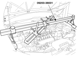
Using the special tool (09200-38001), support the engine assembly safely.
Remove the transaxle upper mounting bolts (A-2ea) and the starter motor mounting bolts (B-2ea).
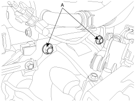
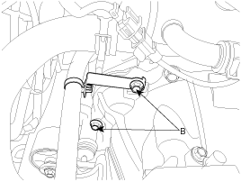
Remove the transaxle support bracket bolts (2ea).
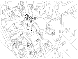
Lift the vehicle.
Remove the front wheels and tires.
Remove the lower arm ball joint mounting nut and the stabilizer link mounting nut from the front knuckles.
(refer to Front suspension system in SS group)
Remove the under shield cover (A).
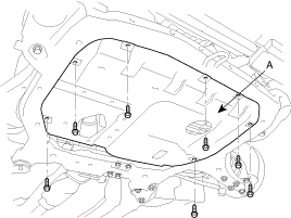
Drain the transalxe fluid by removing the drain plug (A).
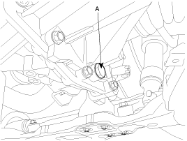
Remove the drive shafts from the transaxle. (Refer to Front Driveshaft in DS group)
Remove the dust cover by removing the bolts(2ea).
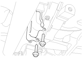
Remove the intercooler pipe (A).
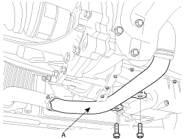
Remove the roll stopper bracket by removing bolts (A,B).
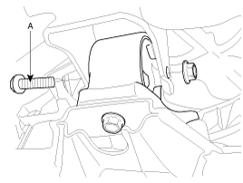
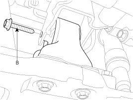
Remove the clutch release cylinder assembly (A).
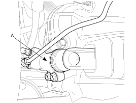
Remove the bolt (A) left in the engine side.
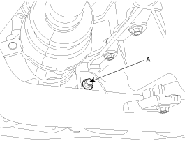
Supporting the transaxle with a jack, remove the transaxle lower mounting bolts (A-3ea, B-1ea).
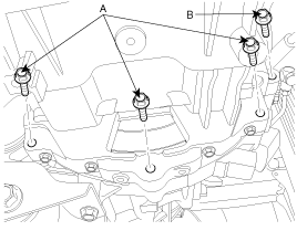
Lowering the jack slowly, remove the transaxle.
Install the transaxle lower mounting bolts (A-3ea,B-1ea) after fitting the transaxle assembly into the engine assembly.
Tightening torque :
[A] 35~50 N.m (3.5~5.0 kgf.m, 25.3~36.2 lb-ft)
[B] 43~55 N.m (4.3~5.5 kgf.m, 31.1~39.8 lb-ft)

Install the bolt (A) left in the engine side.
Tightening torque :
43~55 N.m (4.3~5.5 kgf.m, 31.1~39.8 lb-ft)

Install the clutch release cylinder assembly (A).
Tightening torque :
15~22 N.m (1.5~2.2 kgf.m, 10.8~15.9 lb-ft)

Install the roll stopper bracket by installing bolts (A,B).
Tightening torque :
50~65 N.m (5.0~6.5 kgf.m, 36.2~47.0 lb-ft)


Install the intercooler pipe (A).

Install the dust cover by installing the bolts(2ea).

Install the drive shafts to the transaxle. (Refer to Front Driveshaft in DS group)
Refill the transaxle fluid through the filler hole. (Refer to Service Adjustment Procedure)
Install the under shield cover (A).

Install the lower arm ball joint mounting nut and the stabilizer link mounting nut to the front knuckles.
(Refer to Front suspension system in SS group)
Install the front wheels and tires.
Install the transaxle support bracket bolts (2ea).
Tightening torque :
60~80 N.m (6.0~8.0 kgf.m, 43.4~57.9 lb-ft)

Install the transaxle upper mounting bolts (A-2ea) the starter motor mounting bolts (B-2ea).
Tightening torque :
[A] 60~80 N.m (6.0~8.0 kgf.m, 43.4~57.9 lb-ft)
[B] 39~60 N.m (3.9~6.0 kgf.m, 28.2~43.4 lb-ft)


Put aside the engine support fixture (09200-38001).
After installing the bracket mounting bolt (C), install the clutch tube (B) with the clip (A).
Tightening torque :
15~22 N.m (1.5~2.2 kgf.m, 10.8~15.9 lb-ft)

Install the CKP sensor by installing a bolt.

Install the control cable bracket by installing bolts(3ea).
Tightening torque :
15~22 N.m (1.5~2.2 kgf.m, 10.8~15.9 lb-ft)

Install the clips (B) and pins (A).

Connect the neutral switch connector (A).

Install the ground wire by installing a bolt.

Connect the vehicle speed sensor connector (A) and the back lamp switch connector (B).

Install the air intake hose (A) and the air cleaner assembly (B) after connecting the connector (C) and the ECM connector (D).

Install the radiator grill upper cover (A) and the air duct (B).

Install the battery tray (A) after removing the bolts.

Install the battery (A) and connect the negative battery terminal.
