Hold the sensor and the seal washer, then extract it, this also extracts the seal. Take care to not damage the valve thread.
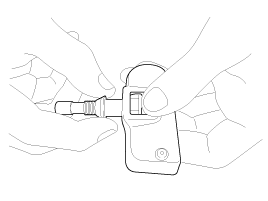
Hold the sensor and the seal washer, then extract it, this also extracts the seal. Take care to not damage the valve thread.

Clean the sensor and the valve stem holding the valve using a dry cloth as shown on the picture. Take care to support the rear of the valve with a thumb so that there is no movement of the stem.
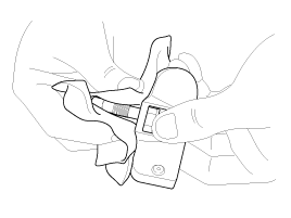
When removing the sensor, a new washer and seal must be used. Insert these up to the base of the sensor, making sure to secure the valve base with a thumb, as shown. Wipe the seal and threading.
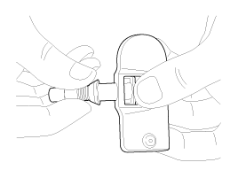
Insert the valve, in the valve hole, without modifying the angle of the stem (retain position of delivery). The laser marking should be visible to the operator.
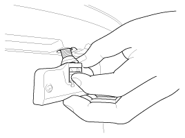
When the valve is completely inserted, maintain the sensor in contact with the rim (as shown on the picture), then screw manually the nut until it is in contact with the wheel (without force).
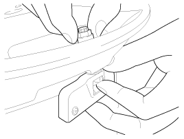
While maintaining the sensor contact with the rim by applying pressure to the back of the valve, slightly press on the cap towards the center of the wheel in order to adapt the angle of the valve/sensor to the profile of the rim. It is mandatory to guarantee the contact of the housing unit on the rim drop center.
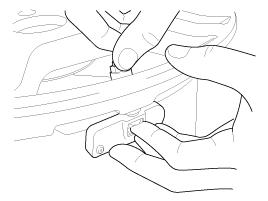
While maintaining the sensor unit and valve in position, screw the nut with a torque wrench.
Apply a torque of 7.5 ~ 8.5Nm (0.76 ~ 0.86kgf.m, 5.5 ~ 6.2lb-ft).
Take care that the wrench socket is correctly inserted on the nut.
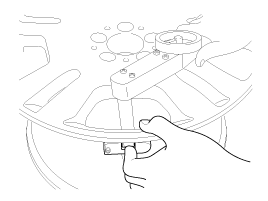
Check the followings.
It is normal that the seal washer becomes bent during the nut tightening.
Check that the visible part of the antenna is not damaged or broken.
The plastic bridge should neither be cracked nor broken. It is designed so that it will fracture due to an error in the assembly process (too high torque, bad positioning……). Any defect must mean the rejection of the sensor.
Before any tire mounting operation, make sure that the sensor has been correctly mounted and tightened to the rim.
No lubricant product or any other material may partially or completely cover the air pressure inlet hole of the sensor.
The assembly tools have to never have a collision with the sensor.
The tire cannot be in contact with the sensor only after it is engaged in the rim and after the exceeded peak of traction. Therefore, generally at the end of the assembly.
Prepare the tire and fix the rim as usual.
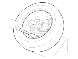
Put the tire on the rim, so that the cross point of the belt with the rim is between 15 and 20 cm away from the valve (see the picture).
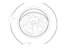
Engage the shoe and make sure that 20cm is maintained between the cross point and the valve. The arrow shows the direction of rotation of the wheel.
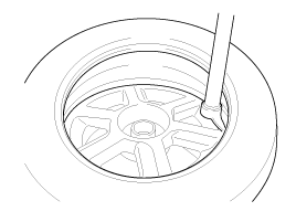
Turn the wheel in order to engage all the first side of the tire.
The standard shoes can pass over the sensor without damaging it.
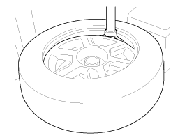
Put the second side of the tire in position, so that the cross point of the belt with the rim is approximately 20 cm away from the valve (see the picture). The curved arrow shows the direction of rotation of the wheel.
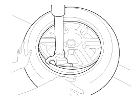
Turn the wheel in order to engage all of the second side of the tire.
The standard shoes can pass over the sensor without damaging it.
Perform the Register Sensor procedure.
(Refer to Register Sensor.)