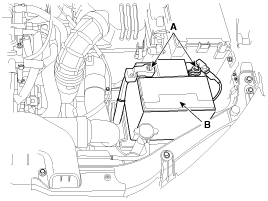
Disconnect the terminals (A) from battery and remove the battery.
Engine removal is not required for this procedure.
Use Fender cover to avoid damaging painted surfaces.
To avoid damaging the cylinder head, wait until the engine coolant temperature drops below normal temperature before removing it.
When handling a metal gasket, take care not to fold the gasket or damage the contact surface of the gasket.
To avoid damage, unplug the wiring connectors carefully while holding the connector portion.
Mark all wiring and hoses to avoid misconnection.
Turn the crankshaft pulley so that the No. 1 piston is at top dead center.
Disconnect the terminals (A) from battery and remove the battery.

Remove the radiator cap to speed draining.
Remove the under cover (A).
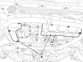
Loosen the radiator drain plug (A) and drain engine coolant.
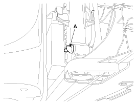
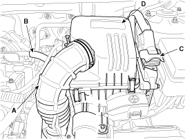
Remove the air duct (A).
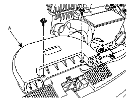
Remove the intake air hose (A) and air cleaner assembly.
Disconnect the breather hose (B) from intake air hose (A).
Disconnect the PCM connector (C).
Remove the air cleaner assembly (D).
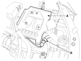
Remove the battery tray (A) and disconnect the front connector (B).
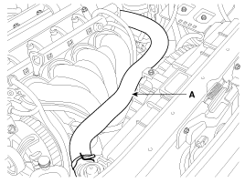
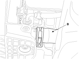
Remove the upper radiator hose (A) and lower radiator hose (B).
Loosen the water pump mounting bolt and the drive idler mounting bolt.
Loosen the alternator tension adjusting bolt (A) to loosen tension.
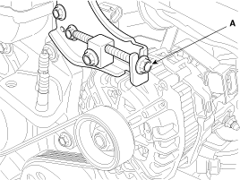
Remove the alternator drive belt (A).
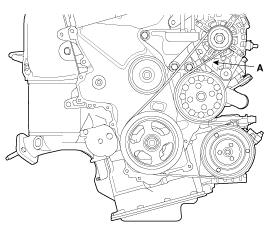
Remove the alternator (A). (Refer to Alternator in EE Group).
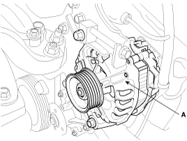
Remove the RH front wheel.
Remove the engine mounting bracket (A) and the ground line (B).
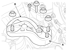
Support the engine with a jack not to be tilted.
Do not support the engine - transaxle - subframe assembly with the hangers.
Remove the alternator bracket.
Remove the engine support bracket (A).
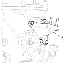
Remove the water pump pulley (A).
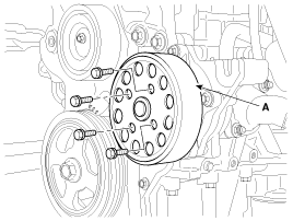
Remove the water pump (A).
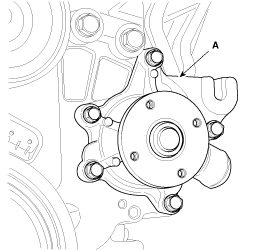
Remove the drive belt idler (A).
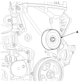
Disconnect the ignition coil connector (A) and the breather hose (B).
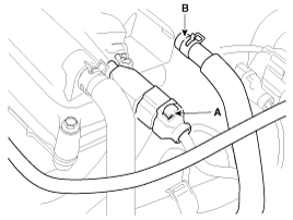
Disconnect the positive crankcase ventilation (PCV) hose (A), and PCSV hose (B).
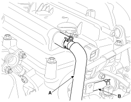
Remove the engine wire harness connectors and wire harness clamps from cylinder head and the intake manifold.
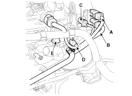
Disconnect the front (A) and the rear (B) oxygen sensor connector.
Disconnect the ignition coil condenser connector (C) and the purge control solenoid valve(PCSV) connector (D).
Disconnect the engine coolant temperature sensor(ECTS) connector (E).
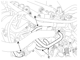
Disconnect the electronic throttle control (ETC) connector (A).
Disconnect the vapor hose (B) and the throttle body coolant hose (C).
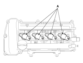
Remove the ignition coil (A).
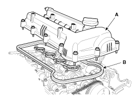
Remove the cylinder head cover (A) with its gasket (B).
Remove side cover.
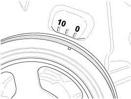
Turn the crankshaft pulley clockwise, and align its groove with the timing mark of the timing chain cover.
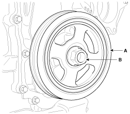
Remove the crankshaft bolt (B) and crankshaft pulley (A).
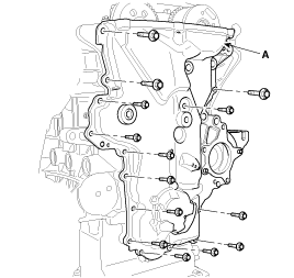
Remove the timing chain cover (A).
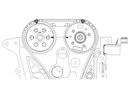
Align the timing marks of the camshaft sprocket with the upper surface of the cylinder head to make No.1 cylinder be positioned at TDC.
Check the dowel pin of the crankshaft for facing upside of the engine at this monent.
Put paint marks on the timing chain links(3places) that meet with the timing marks of the camshaft sprockets(In, Ex : 2) and the crankshaft sprocket.
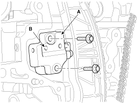
Remove the hydraulic tensioner (A).
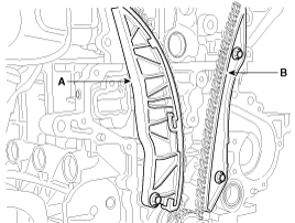
Remove the timing chain tensioner arm (A) and guide (B).
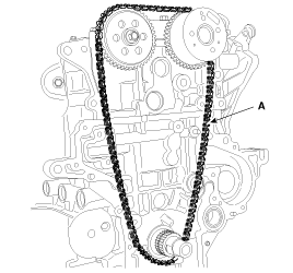
Remove the timing chain (A).
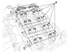
Remove the camshaft bearing caps (A) with the order below.
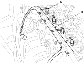
Remove the injector connectors (A) and the harness bracket (B).
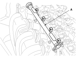
Remove the delivery pipe (A).
Remove the exhaust manifold assembly.
Remove the intake manifold module assembly.
Disconnect the camshaft position sensor (CMP) connector (A) and remove the purge control solenoid valve (PCSV) bracket (B) and the module hanger bracket (C).
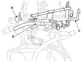
Remove the water temperature control assembly and the oil control valve (OCV).
Remove the cylinder head bolts, then remove the cylinder head.
Uniformly loosen and remove the 10 cylinder head bolts, in several passes, in the sequence shown.
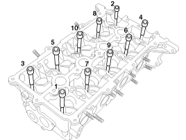
Head warpage or cracking could result from removing bolts in an incorrect order.
Lift the cylinder head from the cylinder block and put the cylinder head on wooden blocks.
Be careful not to damage the contact surfaces of the cylinder head and cylinder block.