
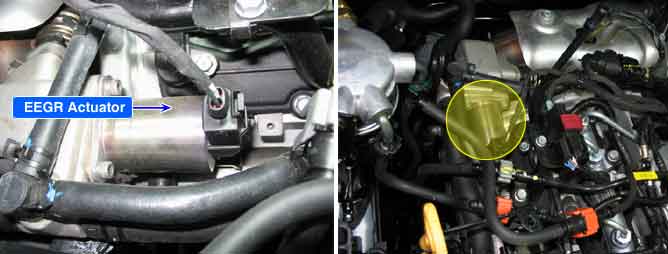
Receiving ECM signal, linear solenoid type electronic EGR actuator operates EEGR valve directly. ECM performs EGR system feed back control with the information of measured mass air flow. (The role of MAFS in diesel engine is different from gasoline engine. Fuel injection quantity is decided by MAFS signal in gasoline engine.) When EGR gas (contains no oxygen) flowing into combustion chamber increases, the air passing through MAFS (contains oxygen) decreases. Thus, with the output signal change of MAFS accompanied by EEGR actuator actuation, ECM determine the amount of recirculated EGR gas quantity.
EGR actuator operation is stopped when one of following conditions is met.
1. Engine coolant temperature is below 15 ℃ or over 100 ℃.
2. Air temperature is below 18 ℃, or over 45 ℃.
3. Idle rpm is below 1000rpm for more than 60 sec.
4. Barometer is below 750hPa. (Altitude is over 2500m)
5. Fuel amount is over 58.4 ㎣.
6. A/C ON.
7. Engine rpm is over 2500 rpm.
NOx is produced from the reaction of nitrogen and oxygen. Controlling EGR gas (contains no oxygen) which is recirculated to combustion chamber, if least intake air required for complete combustion flows into combustion chamber, NOx decreases because there is no supplementary oxygen to react with nitrogen.
P0490 is set when excessive current is detected in EEGR actuator circuit for more than 0.5 sec.. This code is due to short to battery in EEGR actuator control circuit or internal short in EEGR component.
Item | Detecting Condition | Possible Cause | ||
DTC Strategy |
•
Voltage Monitoring |
•
EEGR circuit.
•
EEGR | ||
Enable Conditions |
•
Engine running | |||
Threshold Value |
•
Short to battery in circuit. | |||
Diagnostic Time |
•
500ms | |||
Fail Safe | Fuel cut | NO |
•
It is monitored when power supply is normal. | |
EGR Off | YES | |||
Fuel Limit | NO | |||
Check Lamp | OFF | |||
EEGR Actuator resistance | EEGR Actuator operating Hz | EEGR Actuator operating duty |
7.3 ~ 8.3 Ω (20℃) | 140 Hz | 5%(close) ~ 80%(open) |
Fig.1) It is signal waveform that shows operating duty 4%, 140Hz signal by EGR actuator while EGR actuator is displayed on the scan tool as 4% at idle.
Fig.2) It shows that signal waveform of EEGR actuator with 50% operating duty, 140Hz while EGR actuator is displayed as 50% on sensor data at idle.
☞ The reason that duty is generated at the range of EEGR actuator inactivated is to diagnose EEGR circuit not to operate EEGR actuator.