
The PCM/TCM controls the locking and unlocking of the Torque Converter Clutch ( or Damper Clutch ), to the input shaft of the transmission, by appling hydraulic pressure. The main purpose of T/C clutch control is to save fuel by decreasing the hydraulic load inside the T/C. The PCM/TCM outputs duty pulses to control the Damper Clutch Control Solenoid Valve( DCCSV ) and hydraulic pressure is applied to the DC according to the DCC duty ratio value. When the duty ratio is high, high pressure is applied and the Damper Clutch is locked.
TCM set this code If supply voltage to solenoid is lower than available range.(MIL ON : 2 driving Cycle)
Item | Detecting Condition | Possible Cause | |
DTC Strategy |
•
Check function |
•
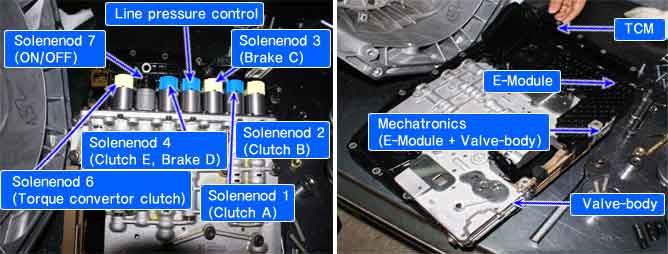
Faulty in Torque convertor
•
Mechatronics(E-module + Valvebody) | |
Enable Conditions | CASE1 |
•
Torque convertor clutch solenoid continuously OFF | |
CASE2 |
•
OFF operation mode | ||
Threshold Value | CASE1 |
•
Average set-up value - Actual value > 40RPM (Faulty in Torque convertor) | |
CASE2 |
•
Solenoid output voltage - Solenoid supply voltage < 0.5V (Faulty in Torque convertor clutch solenoid) | ||
Diagnostic Time |
•
2 second | ||
Fail Safe |
•
No Torque convertor clutch control(CASE 1)
•
Shifting from 1st to 6th gear
•
No learning control (priority : 3) | ||
The function with the higher priority will aiways take precedence. However, a low-priority is not overruled by a higher priority function.
Functions from different priority categories can also run in parallel. It is important to note which function will take precedence in this case.
In such an event it is possible for a substitute function with low priority not be carried out if a second, higher-priority function is present. This has been taken into account when compiling the priority list and is international.
The mechanical emergency run function must always have the highest priority, since from the electrical standpoint it is the only safe condition.
gear position | ON SOL. | SOL.1 | SOL.2 | SOL.3 | SOL. 4 | SOL. 5 | SOL. 6 |
P | OFF | 48mA | 848mA | 48mA | 48mA | -O- | OFF |
R | OFF | 48mA | 48mA | 48mA | 48mA | -O- | OFF |
N | OFF | 48mA | 848mA | 48mA | 48mA | -O- | OFF |
D1 | OFF | 848mA | 848mA | 48mA | 48mA | -O- | -O- |
D2 | OFF | 848mA | 848mA | 848mA | 848mA | -O- | -O- |
D3 | OFF | 848mA | 48mA | 48mA | 848mA | -O- | -O- |
D4 | ON | 848mA | 848mA | 48mA | 48mA | -O- | -O- |
D5 | ON | 48mA | 48mA | 48mA | 48mA | -O- | -O- |
D6 | ON | 48mA | 848mA | 848mA | 48mA | -O- | -O- |
-O- : variable control

Fig 1) Lock-up status of Torque convertor clutch in 3rd gear.
Fig 2) Release the Lock-up at 3rd to 4th gear shifting
Fig 3) Release the Lock-up status in 5th gear
Fig 4) Lock-up status in 5th gear
Fig 5) Lock-up status in 6th gear