
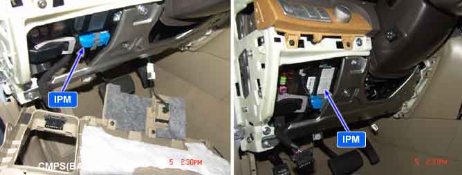
This is DTC which is related with communication error between IPM and other units.
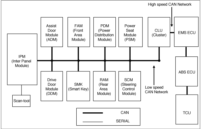
(※ Control Units : IPM(Inter Panel Module), FAM(Front Area Module), PDM(Power Distribution Module), DDM(Drive Door Module), ADM(Assist Door Module), CLU(Cluster), PSM(Power Seat Module), SCM(Steering Control Module), RAM(Rear Area Module), SMK(Smart Key)
*¹ CAN (Controller Area Network) : CAN is serial bus communication type which links not only communication system but also control units each other.
*² LIN (Local Interconnect Network) : LIN is serial communication type which is used in electrical control system.
IPM sets DTC when EEPRM of Micom in IPM is read / write error.
Item | Detecting Condition | Possible Cause |
DTC Strategy |
•
Check EEPROM read / write status |
•
Faulty IPM |
Enable Conditions |
•
IG ON | |
Threshold Value |
•
EEPROM read / write error | |
Diagnostic Time |
•
Immediately | |
DTC Erasing Time |
•
DTC is erased immediately after trouble fixed (In case of the past error, perform DTC erasing procedure.) |
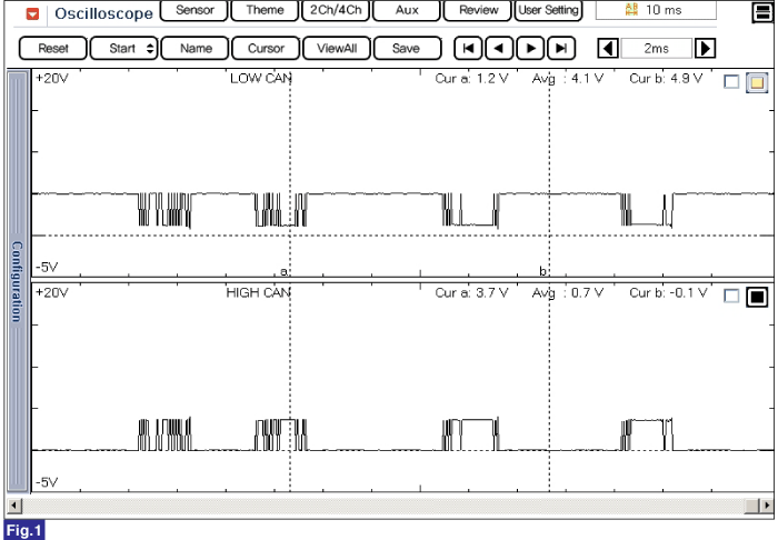
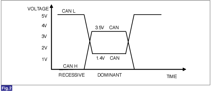
Fig 1) Signal waveform of CAN Low and HIGH
Fig 2) CAN BUS VOLTAGE LEVEL (LOW SPEED CAN)