
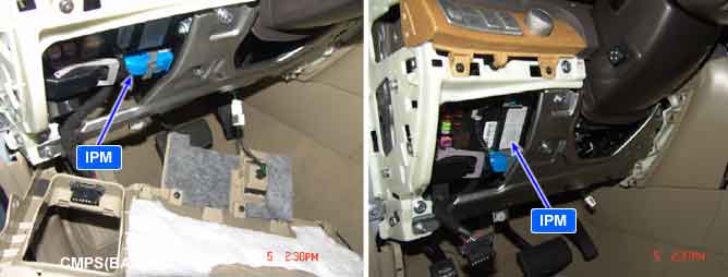
All 13 units which consists of the Body Electrical Control System are linked by CAN*¹ line.
They are IPM(Inter Panel Module), FAM(Front Area Module), PDM(Power Distribution Module), DDM(Drive Door Module), ADM(Assist Door Module), ECW(Electronic Control Wiper), CLU(Cluster), MFSW(Multi Function Switch), PSM(Power Seat Module), SCM(Steering Control Module), PTM(Power Trunk Lid Module), FBWS(Front Back Warning System), DATC(Dual Auto Temperature Control Module).
*¹ CAN (Controller Area Network) : CAN is serial bus communication type which links not only communication system but also control units each other.
*² LIN (Local Interconnect Network) : LIN is serial communication type which is used in electrical control system.
Pattern | Status | Communication is normal but DTC set if IPM detects 7 error status as follows. ① Short to battery in CAN High circuit ② Short to ground in CAN High circuit ③ Short to battery in CAN Low circuit ④ Short to ground in CAN Low circuit ⑤ Short between CAN High and Low circuit ⑥ Open or Poor connection in CAN Low circuit ⑦ Open or Poor connection in CAN High circuit |
1 | Open in CAN High circuit | |
2 | Open in CAN Low circuit | |
3 | Short to battery in CAN High circuit | |
4 | Short to battery in CAN Low circuit | |
5 | Short to ground in CAN High circuit | |
6 | Short to ground in CAN Low circuit | |
7 | Short between CAN High and Low circuit |
Item | Detecting Condition | Possible Cause | ||
DTC Strategy |
•
CAN communication status |
•
Short to battery / ground in CAN high circuit
•
Short to battery / ground in CAN low circuit
•
Short between CAN high and CAN low circuit
•
Open or poor connection in CAN high and low circuit
•
Faulty IPM | ||
Enable Conditions |
•
IG "ON"
•
Engine "START"
•
B/T voltage engerzied to IPM | |||
Threshold Value | CAN high | 0 V | Short to ground | |
B+ V | Short to battery | |||
CAN low | 0 V | Short to ground | ||
B+ V | Short to battery | |||
Diagnostic Time |
•
Failure continues for 2sec. | |||
DTC Erasing Time |
•
DTC is erased immediately after trouble fixed (In case of the past error, perform DTC erasing procedure.) | |||
Fig 1) Signal waveform of CAN Low and HIGH
Fig 2) CAN BUS VOLTAGE LEVEL (LOW SPEED CAN)