
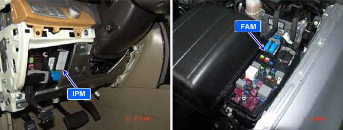
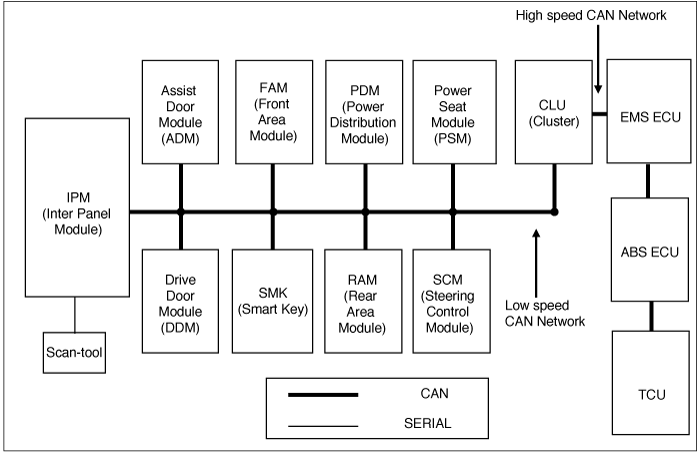
All 10 units which consists of the Body Electrical Control System are linked by CAN*¹ line.
They are IPM(Inter Panel Module), FAM(Front Area Module), PDM(Power Distribution Module),
DDM(Drive Door Module), ADM(Assist Door Module), CLU(Cluster), PSM(Power Seat Module),
SCM(Steering Control Module), RAM(Rear Area Module), SMK(Smart Key).
*¹ CAN (Controller Area Network) : CAN is serial bus communication type which links not only communication system but also control units each other.
*² LIN (Local Interconnect Network) : LIN is serial communication type which is used in electrical control system.
"B1627" is set when FAM detects faulty data in EEPROM.
Item | Detecting Condition | Possible Cause |
DTC Strategy |
•
EEPROM data state check |
•
Faulty FAM |
Enable Conditions |
•
ACC "ON" | |
Threshold Value |
•
Faulty EEPROM data | |
Diagnostic Time |
•
Immediately | |
DTC Erasing Time |
•
DTC is erased immediately after trouble fixed. |
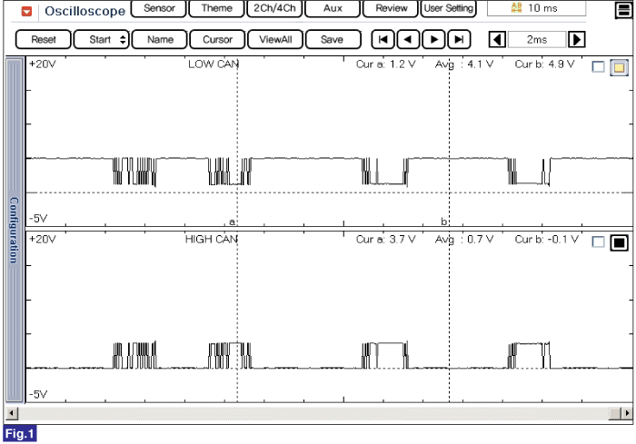
Fig 1) CAN Low/High Signal
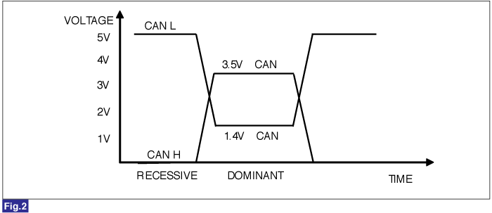
Fig 2) CAN BUS VOLTAGE LEVEL (LOW SPEED CAN)