
All 10 units which consists of the Body Electrical Control System are linked by CAN*¹ line.
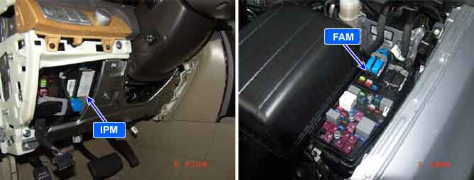
They are IPM(Inter Panel Module), FAM(Front Area Module), PDM(Power Distribution Module),
DDM(Drive Door Module), ADM(Assist Door Module), CLU(Cluster), PSM(Power Seat Module),
SCM(Steering Control Module), RAM(Rear Area Module), SMK(Smart Key).
*¹ CAN (Controller Area Network) : CAN is serial bus communication type which links not only communication system but also control units each other.
*² LIN (Local Interconnect Network) : LIN is serial communication type which is used in electrical control system.
"B1646" is set in case of CAN communication failure due to either FAM, RAM not existing at CAN line or IPM, FAM, RAM internal fault.
Item | Detecting Condition | Possible Cause |
DTC Strategy |
•
Network state check |
•
CAN Line check
•
FAM, IPM, RAM operation check |
Enable Conditions |
•
ACC "ON" | |
Threshold Value |
•
RF Module being not in accordance with regional frequency installed | |
Diagnostic Time |
•
Immediately | |
DTC Erasing Time |
•
DTC is erased immediately after trouble fixed. |
Fig 1) CAN Low/High Signal
Fig 2) CAN BUS VOLTAGE LEVEL (LOW SPEED CAN)