
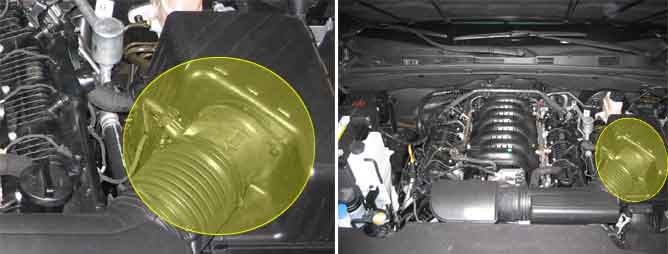
The Intake Air Temperature Sensor (IATS) is installed into the Mass Air Flow Sensor (MAFS). The IATS uses a thermistor whose resistance changes with the temperature. The electrical resistance of the IATS decreases as the temperature increases, and increases as the temperature decreases. The 5 V power source in the ECM is supplied to the IATS via a resistor in the ECM. That is, the resistor in the ECM and the thermistor in the IATS are connected in series. When the resistance value of the thermistor in IATS changes according to the intake air temperature, the signal voltage also changes. Using this signal, the information of the intake air temperature, the ECM corrects basic fuel injection duration and ignition timing.
ECM monitors temperature changes resulting from soaking the vehicle.
Therefore, Coolant temperature and Intake temperature should be changed.
If ECM detects intake air temperature correlated to coolant temperature does not change ECM determines that a fault exists and a DTC is stored.
Item | Detecting Condition | Possible Cause | |
DTC Strategy |
•
Rationality check |
•
Poor connection
•
Short to ground in signal circuit
•
Open in ground circuit
•
Faulty ECTS
•
Faulty IATS
•
Faulty ECM | |
Case1 | Enable Conditions |
•
Vehicle speed < 3mph for 14sec ≥ 6 times
•
Vehicle speed > 30mph for 8sec ≥ 2 times | |
Threshold Value |
•
Max. temp – Min. temp < 1.5℃ | ||
Case2 | Enable Conditions |
•
Vehicle speed > 30 mph
•
60 ≤ Airflow ≤ 300 Kg/h | |
Threshold Value |
•
Measured temperature > 115C | ||
Diagnostic Time |
•
2 sec | ||
Case3 | Enable Conditions |
•
Cold Start Check ECT at Start : -30C <ECT< 45C ECT at the end of last trip > 80C
•
Block Heater Check ETC < 50C ECT - ECT at Start < -3C | |
Threshold Value |
•
IAT - ECT > 20C | ||
MIL ON Condition |
•
NO MIL | ||
Temp. (℃) | Resistance (kΩ) | Temp. (℃) | Resistance (kΩ) |
-40 | 95.95 ~ 105.78 | 20 | 3.42 ~ 3.61 |
-20 | 27.4 ~ 29.77 | 40 | 1.43 ~ 1.5 |
0 | 9.08 ~ 9.72 | 60 | 0.66 ~ 0.69 |
10 | 5.49 ~ 5.83 | 80 | 0.33 ~ 0.34 |
