
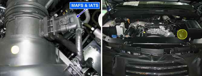
Mass Air Flow Sensor (MAFS) is digital sensor. Measuring mass of air flow, signal is outputted as frequency (Hz). ECM performs EGR system feed back control with the information of measured mass air flow. (The role of MAFS in diesel engine is different from gasoline engine. Fuel injection quantity is decided by MAFS signal in gasoline engine.) When the amount of EGR gas (contains no oxygen) flowing into combustion chamber increases, the air passing through MAFS (contains oxygen) decreases. Thus, with the output signal change of MAFS accompanied by EGR actuator actuation, ECM determines the amount of recirculated EGR gas quantity.
NOx is produced in the reaction of nitrogen and oxygen. If least intake air required for complete combustion flows into combustion chamber by controlling EGR gas (contains no oxygen) which is recirculated to combustion chamber, NOx decreases because there is no supplementary oxygen to react with nitrogen.
In case of replacing MAFS, perform the "COMPONENT CHANGE ROUTINE" procedure with GDS. If the "COMPONENT CHANGE ROUTINE" procedure has not completed until automatic learning completed, it may cause vehicle performance and exhaust gas problem.
P0101 is set 1) when Air mass ratio (real/threshold) above 1.37 or below 0.87 is detected or 2) short to battery or ground in MAFS or IATS signal circuit is detected or 3) short to low or high voltage line in IATS signal circuit is detected.
Item | Detecting Condition | Possible Cause | |||
DTC Strategy |
•
Voltage monitoring |
•
MAFS circuit
•
MAFS | |||
Enable Conditions |
•
Engine running | ||||
Case 1 | Threshold Value |
•
Short to battery in MAFS circuit. | |||
Diagnostic Time |
•
0.6 sec | ||||
Case 2 | Threshold Value |
•
Real MAFS value is 15% higher than target value. | |||
Diagnostic Time |
•
2 sec | ||||
Case 3 | Threshold Value |
•
Real MAFS value is 71% lower than target value. | |||
Diagnostic Time |
•
2 sec | ||||
Fail Safe | Fuel cut | NO |
•
MIL is ON when case 2 and case 3 is satisfied. | ||
EGR Off | YES | ||||
Fuel Limit | YES | ||||
Check Lamp | OFF | ||||
Intake air amount | Output frequency(20℃) | Output frequency(80℃) |
10 kg/h | 1.936 ~ 1.942 kHz | 1.933 ~ 1.945 kHz |
15 kg/h | 1.997 ~ 2.007 kHz | - |
20 kg/h | 2.060 ~ 2.069 kHz | - |
90 kg/h | 2.668 ~ 2.692 kHz | 2.654 ~ 2.705 kHz |
220 kg/h | 3.425 ~ 3.473 kHz | 3.440 ~ 3.498 kHz |
440 kg/h | 4.653 ~ 4.761 kHz | 4.599 ~ 4.816 kHz |
850 kg/h | 7.873 ~ 8.255 kHz | - |
1000kg/h | 9.6 ~ 10.525 kHz | - |
Fig. 1) Signal waveform of MAFS at idle.
Fig. 2) Signal waveform of MAFS at 3000rpm.
☞ The higher engine rpm, the higher output frequency.
Fig. 3) Reference signal waveform which is outputted in of 'ATS signal' terminal 'AIR FLOW SENSOR'.